9.2: Electrical Current
( \newcommand{\kernel}{\mathrm{null}\,}\)
By the end of this section, you will be able to:
- Describe an electrical current
- Define the unit of electrical current
- Explain the direction of current flow
Up to now, we have considered primarily static charges. When charges did move, they were accelerated in response to an electrical field created by a voltage difference. The charges lost potential energy and gained kinetic energy as they traveled through a potential difference where the electrical field did work on the charge.
Although charges do not require a material to flow through, the majority of this chapter deals with understanding the movement of charges through a material. The rate at which the charges flow past a location—that is, the amount of charge per unit time—is known as the electrical current. When charges flow through a medium, the current depends on the voltage applied, the material through which the charges flow, and the state of the material. Of particular interest is the motion of charges in a conducting wire. In previous chapters, charges were accelerated due to the force provided by an electrical field, losing potential energy and gaining kinetic energy. In this chapter, we discuss the situation of the force provided by an electrical field in a conductor, where charges lose kinetic energy to the material reaching a constant velocity, known as the “drift velocity.” This is analogous to an object falling through the atmosphere and losing kinetic energy to the air, reaching a constant terminal velocity.
If you have ever taken a course in first aid or safety, you may have heard that in the event of electric shock, it is the current, not the voltage, which is the important factor on the severity of the shock and the amount of damage to the human body. Current is measured in units called amperes; you may have noticed that circuit breakers in your home and fuses in your car are rated in amps (or amperes). But what is the ampere and what does it measure?
Defining Current and the Ampere
Electrical current is defined to be the rate at which charge flows. When there is a large current present, such as that used to run a refrigerator, a large amount of charge moves through the wire in a small amount of time. If the current is small, such as that used to operate a handheld calculator, a small amount of charge moves through the circuit over a long period of time.
The average electrical current I is the rate at which charge flows,
Iave=ΔQΔt,
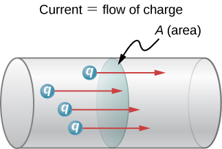
where ΔQ is the amount of net charge passing through a given cross-sectional area in time Δt (Figure 9.2.1). The SI unit for current is the ampere (A), named for the French physicist André-Marie Ampère (1775–1836). Since I=ΔQΔt, we see that an ampere is defined as one coulomb of charge passing through a given area per second:
1A≡1Cs.
The instantaneous electrical current, or simply the electrical current, is the time derivative of the charge that flows and is found by taking the limit of the average electrical current as Δt→0.
I=limΔt→0ΔQΔt=dQdt.
Most electrical appliances are rated in amperes (or amps) required for proper operation, as are fuses and circuit breakers.
The main purpose of a battery in a car or truck is to run the electric starter motor, which starts the engine. The operation of starting the vehicle requires a large current to be supplied by the battery. Once the engine starts, a device called an alternator takes over supplying the electric power required for running the vehicle and for charging the battery.
- What is the average current involved when a truck battery sets in motion 720 C of charge in 4.00 s while starting an engine?
- How long does it take 1.00 C of charge to flow from the battery?
Strategy
We can use the definition of the average current in Equation ??? to find the average current in part (a), since charge and time are given. For part (b), once we know the average current, we use Equation ??? to find the time required for 1.00 C of charge to flow from the battery.
Solution
a. Entering the given values for charge and time into the definition of current gives
I=ΔQΔt=720C4.00s=180C/s=180A.
b. Solving the relationship I=ΔQΔt for time Δt and entering the known values for charge and current gives
Δt=ΔQI=1.00C180C/s=5.56×10−3s=5.56ms.
Significance
- This large value for current illustrates the fact that a large charge is moved in a small amount of time. The currents in these “starter motors” are fairly large to overcome the inertia of the engine.
- A high current requires a short time to supply a large amount of charge. This large current is needed to supply the large amount of energy needed to start the engine.
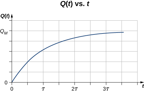
Consider a charge moving through a cross-section of a wire where the charge is modeled as Q(t)=QM(1−e−t/τ). Here, QM is the charge after a long period of time, as time approaches infinity, with units of coulombs, and τ is a time constant with units of seconds (Figure 9.2.2). What is the current through the wire?
Strategy
The current through the cross-section can be found from I=dQdt. Notice from the figure that the charge increases to QM and the derivative decreases, approaching zero, as time increases (Figure 9.2.2).
Solution
The derivative can be found using ddxeu=eududx.
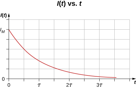
I=dQdt=ddt[QM(1−e−t/τ)]=QMτe−t/τ.
Significance
The current through the wire in question decreases exponentially, as shown in Figure 9.2.3. In later chapters, it will be shown that a time-dependent current appears when a capacitor charges or discharges through a resistor. Recall that a capacitor is a device that stores charge. You will learn about the resistor in Model of Conduction in Metals.
Handheld calculators often use small solar cells to supply the energy required to complete the calculations needed to complete your next physics exam. The current needed to run your calculator can be as small as 0.30 mA. How long would it take for 1.00 C of charge to flow from the solar cells? Can solar cells be used, instead of batteries, to start traditional internal combustion engines presently used in most cars and trucks?
- Answer
-
The time for 1.00 C of charge to flow would be
Δt=ΔQI=1.00C0.300×10−3C/s=3.33×103s.
This is slightly less than an hour. This is quite different from the 5.55 ms for the truck battery. The calculator takes a very small amount of energy to operate, unlike the truck’s starter motor. There are several reasons that vehicles use batteries and not solar cells. Aside from the obvious fact that a light source to run the solar cells for a car or truck is not always available, the large amount of current needed to start the engine cannot easily be supplied by present-day solar cells. Solar cells can possibly be used to charge the batteries. Charging the battery requires a small amount of energy when compared to the energy required to run the engine and the other accessories such as the heater and air conditioner. Present day solar-powered cars are powered by solar panels, which may power an electric motor, instead of an internal combustion engine.
Circuit breakers in a home are rated in amperes, normally in a range from 10 amps to 30 amps, and are used to protect the residents from harm and their appliances from damage due to large currents. A single 15-amp circuit breaker may be used to protect several outlets in the living room, whereas a single 20-amp circuit breaker may be used to protect the refrigerator in the kitchen. What can you deduce from this about current used by the various appliances?
- Answer
-
The total current needed by all the appliances in the living room (a few lamps, a television, and your laptop) draw less current and require less power than the refrigerator.
Current in a Circuit
In the previous paragraphs, we defined the current as the charge that flows through a cross-sectional area per unit time. In order for charge to flow through an appliance, such as the headlight shown in Figure 9.2.4, there must be a complete path (or circuit) from the positive terminal to the negative terminal. Consider a simple circuit of a car battery, a switch, a headlight lamp, and wires that provide a current path between the components. In order for the lamp to light, there must be a complete path for current flow. In other words, a charge must be able to leave the positive terminal of the battery, travel through the component, and back to the negative terminal of the battery. The switch is there to control the circuit. Part (a) of the figure shows the simple circuit of a car battery, a switch, a conducting path, and a headlight lamp. Also shown is the schematic of the circuit [part (b)]. A schematic is a graphical representation of a circuit and is very useful in visualizing the main features of a circuit. Schematics use standardized symbols to represent the components in a circuits and solid lines to represent the wires connecting the components. The battery is shown as a series of long and short lines, representing the historic voltaic pile. The lamp is shown as a circle with a loop inside, representing the filament of an incandescent bulb. The switch is shown as two points with a conducting bar to connect the two points and the wires connecting the components are shown as solid lines. The schematic in part (c) shows the direction of current flow when the switch is closed.
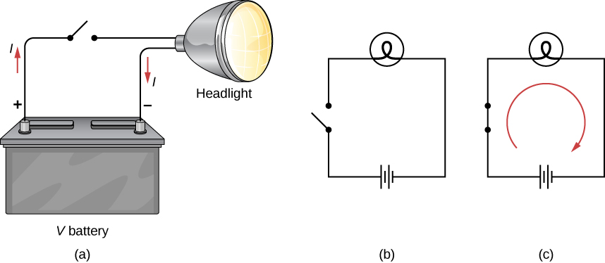
When the switch is closed in Figure 9.2.4c, there is a complete path for charges to flow, from the positive terminal of the battery, through the switch, then through the headlight and back to the negative terminal of the battery. Note that the direction of current flow is from positive to negative. The direction of conventional current is always represented in the direction that positive charge would flow, from the positive terminal to the negative terminal.
The conventional current flows from the positive terminal to the negative terminal, but depending on the actual situation, positive charges, negative charges, or both may move. In metal wires, for example, current is carried by electrons—that is, negative charges move. In ionic solutions, such as salt water, both positive and negative charges move. This is also true in nerve cells. A Van de Graaff generator, used for nuclear research, can produce a current of pure positive charges, such as protons. In the Tevatron Accelerator at Fermilab, before it was shut down in 2011, beams of protons and antiprotons traveling in opposite directions were collided. The protons are positive and therefore their current is in the same direction as they travel. The antiprotons are negativity charged and thus their current is in the opposite direction that the actual particles travel.
A closer look at the current flowing through a wire is shown in Figure 9.2.5. The figure illustrates the movement of charged particles that compose a current. The fact that conventional current is taken to be in the direction that positive charge would flow can be traced back to American scientist and statesman Benjamin Franklin in the 1700s. Having no knowledge of the particles that make up the atom (namely the proton, electron, and neutron), Franklin believed that electrical current flowed from a material that had more of an “electrical fluid” and to a material that had less of this “electrical fluid.” He coined the term positive for the material that had more of this electrical fluid and negative for the material that lacked the electrical fluid. He surmised that current would flow from the material with more electrical fluid—the positive material—to the negative material, which has less electrical fluid. Franklin called this direction of current a positive current flow. This was pretty advanced thinking for a man who knew nothing about the atom.
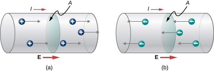
We now know that a material is positive if it has a greater number of protons than electrons, and it is negative if it has a greater number of electrons than protons. In a conducting metal, the current flow is due primarily to electrons flowing from the negative material to the positive material, but for historical reasons, we consider the positive current flow and the current is shown to flow from the positive terminal of the battery to the negative terminal.
It is important to realize that an electrical field is present in conductors and is responsible for producing the current (Figure 9.2.5). In previous chapters, we considered the static electrical case, where charges in a conductor quickly redistribute themselves on the surface of the conductor in order to cancel out the external electrical field and restore equilibrium. In the case of an electrical circuit, the charges are prevented from ever reaching equilibrium by an external source of electric potential, such as a battery. The energy needed to move the charge is supplied by the electric potential from the battery.
Although the electrical field is responsible for the motion of the charges in the conductor, the work done on the charges by the electrical field does not increase the kinetic energy of the charges. We will show that the electrical field is responsible for keeping the electric charges moving at a “drift velocity.”


