
11.4: Waveguides


- Last updated
- Aug 2, 2021
- Save as PDF

( \newcommand{\kernel}{\mathrm{null}\,}\)
Generically, a “waveguide” is a device that forces a traveling wave to propagate only where you want it to go. Typically, a waveguide is some kind of tube that allows the wave disturbance to propagate in one direction while confining it in the other directions. In this section, we will discuss the case of straight wave guides with simple uniform cross sections. The really interesting physics occurs when the width of the waveguide is not much larger than the wavelength of the wave. Then, as we will see, the physics of the waveguide has a dramatic effect on the propagation of the wave.
The simplest situation to discuss is the case of transverse oscillations of a membrane in the form of an infinite strip, as shown in Figure 11.20. Consider a membrane with surface
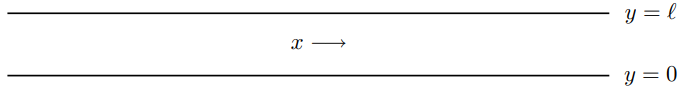
Figure 11.20: A section of an infinite strip of stretched membrane that acts as a waveguide.
mass density ρs and surface tension Ts, stretched in an infinite strip in the x-y plane between y=0 and y=ℓ and from x=−∞ to ∞. The edges, at y=0 and y=ℓ are held fixed in the plane. We are interested in the oscillations of the interior of the strip up and down out of the plane.
This is a job for separation of variables. We can look for modes of this system which are products of a function of x and a function of y. In particular, we can satisfy the boundary conditions at y=0 by combining two modes of the infinite system, eikxxeikyy, and eikxxe−ikyy
into sin(kyy)eikxx.
Now this satisfies the boundary condition at y=ℓ if ky=nπℓ for n=1 to ∞.
Thus the modes look like this: ψn+(x,y,t)=Asinnπyℓei(kxx−ωt),
and ψn−(x,y,t)=Asinnπyℓei(−kxx−ωt).
For each value of n, these look like waves traveling in the 土x direction!
The dispersion relation for the membrane is given by (11.18). But the modes, ψn±, have |ky|=nπℓ. Thus the dispersion relation for the traveling waves, (11.99) and (11.100) is ω2=v2k2x+ω2n,
where v=√Tsρs
and ωn−nπvℓ.
One interesting thing about (11.101) is that the dispersion relation has a low frequency cut-off that depends on n. For any given ω, the only modes that actually propagate are the finite number of modes with n<ωℓπv.
For example, for ω≤πv/ℓ, there are no traveling waves. For πv/ℓ<ω≤2πv/ℓ),thereisonlyone,correspondingto\(n=1, etc.
The modes satisfying (11.104) have a simple physical interpretation. They can be thought of as the plane waves, (11.96), of the infinite system, bouncing back and forth between the fixed edges, y=0 and y=ℓ. The requirement, (11.98), on the allowed values of ky arises because for other values of ky, the reflected waves get out of phase, giving destructive interference. You might expect a zig-zag wave of this kind to propagate in the x direction with a speed less than the phase velocity, v, of the waves in the infinite system by a factor of kx√k2x+k2y=kx√k2x+(ωn/v)2,
because it has to go that much farther as it bounces back and forth to move a given distance in x, as illustrated in Figure 11.21. In fact, the phase velocity of the zig-zag waves for fixed
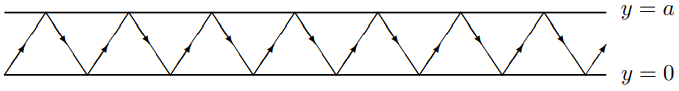
Figure 11.21: A zig-zag wave in the waveguide.
n, ω/kx, is actually larger than v by the factor, (11.105), rather than smaller, vnϕ=ωkx=v√k2x+(ωn/v)2kx.
However, the group velocity, ∂ω/∂kx, of the zig-zag waves, the velocity with which you can actually send signals, is smaller by just the expected factor, vgn=∂ω∂kx=vkx√k2x+(ωn/v)2.
For light waves, we can make a wave guide by making a tube of some conducting material, so that the electric field is nonzero only inside the tube. However, in this case, the details of the boundary conditions at the edges depend on the direction of the electric field. We will return to a related question in the next chapter.