5.7: Common Forces - Stress, Strain and the Spring Force
- Page ID
- 69881

- Explain the concepts of stress and strain in describing elastic deformations of materials
- Describe the types of elastic deformation of objects and materials
- Explain the limit where a deformation of material is elastic
- Describe the range where materials show plastic behavior
- Analyze elasticity and plasticity on a stress-strain diagram
- Define spring forces
A model of a rigid body is an idealized example of an object that does not deform under the actions of external forces. It is very useful when analyzing mechanical systems—and many physical objects are indeed rigid to a great extent. The extent to which an object can be perceived as rigid depends on the physical properties of the material from which it is made. For example, a ping-pong ball made of plastic is brittle, and a tennis ball made of rubber is elastic when acted upon by squashing forces. However, under other circumstances, both a ping-pong ball and a tennis ball may bounce well as rigid bodies. Similarly, someone who designs prosthetic limbs may be able to approximate the mechanics of human limbs by modeling them as rigid bodies; however, the actual combination of bones and tissues is an elastic medium.
For the remainder of this section, we move from consideration of forces that affect the motion of an object to those that affect an object’s shape. A change in shape due to the application of a force is known as a deformation. Even very small forces are known to cause some deformation. Deformation is experienced by objects or physical media under the action of external forces—for example, this may be squashing, squeezing, ripping, twisting, shearing, or pulling the objects apart. In the language of physics, two terms describe the forces on objects undergoing deformation: stress and strain.
Stress is a quantity that describes the magnitude of forces that cause deformation. Stress is generally defined as force per unit area. When forces pull on an object and cause its elongation, like the stretching of an elastic band, we call such stress a tensile stress. When forces cause a compression of an object, we call it a compressive stress. When an object is being squeezed from all sides, like a submarine in the depths of an ocean, we call this kind of stress a bulk stress (or volume stress). In other situations, the acting forces may be neither tensile nor compressive, and still produce a noticeable deformation. For example, suppose you hold a book tightly between the palms of your hands, then with one hand you press-and-pull on the front cover away from you, while with the other hand you press-and-pull on the back cover toward you. In such a case, when deforming forces act tangentially to the object’s surface, we call them ‘shear’ forces and the stress they cause is called shear stress.
The SI unit of stress is the pascal (Pa). When one newton of force presses on a unit surface area of one meter squared, the resulting stress is one pascal:
\[one\; pascal = 1.0\; Pa = \frac{1.0\; N}{1.0\; m^{2}} \ldotp\]
In the British system of units, the unit of stress is ‘psi,’ which stands for ‘pound per square inch’ (lb/in2). Another unit that is often used for bulk stress is the atm (atmosphere). Conversion factors are
\[1\; psi = 6895\; Pa\; and\; 1\; Pa = 1.450 \times 10^{-4}\; psi\]
\[1\; atm = 1.013 \times 10^{5}\; Pa = 14.7\; psi \ldotp\]
An object or medium under stress becomes deformed. The quantity that describes this deformation is called strain. Strain is given as a fractional change in either length (under tensile stress) or volume (under bulk stress) or geometry (under shear stress). Therefore, strain is a dimensionless number. Strain under a tensile stress is called tensile strain, strain under bulk stress is called bulk strain (or volume strain), and that caused by shear stress is called shear strain.
The greater the stress, the greater the strain; however, the relation between strain and stress does not need to be linear. Only when stress is sufficiently low is the deformation it causes in direct proportion to the stress value. The proportionality constant in this relation is called the elastic modulus. In the linear limit of low stress values, the general relation between stress and strain is
\[stress = (elastic\; modulus) \times strain \ldotp \label{12.33}\]
As we can see from dimensional analysis of this relation, the elastic modulus has the same physical unit as stress because strain is dimensionless.
We can also see from Equation \ref{12.33} that when an object is characterized by a large value of elastic modulus, the effect of stress is small. On the other hand, a small elastic modulus means that stress produces large strain and noticeable deformation. For example, a stress on a rubber band produces larger strain (deformation) than the same stress on a steel band of the same dimensions because the elastic modulus for rubber is two orders of magnitude smaller than the elastic modulus for steel.
The elastic modulus for tensile stress is called Young’s modulus; that for the bulk stress is called the bulk modulus; and that for shear stress is called the shear modulus. Note that the relation between stress and strain is an observed relation, measured in the laboratory. Elastic moduli for various materials are measured under various physical conditions, such as varying temperature, and collected in engineering data tables for reference (Table \(\PageIndex{1}\)). These tables are valuable references for industry and for anyone involved in engineering or construction. In the next section, we discuss strain-stress relations beyond the linear limit represented by Equation \ref{12.33}, in the full range of stress values up to a fracture point. In the remainder of this section, we study the linear limit expressed by Equation \ref{12.33}.
| Material | Young’s modulus × 1010 Pa | Bulk modulus × 1010 Pa | Shear modulus × 1010 Pa |
|---|---|---|---|
| Aluminum | 7.0 | 7.5 | 2.5 |
| Bone (tension) | 1.6 | 0.8 | 8.0 |
| Bone (compression) | 0.9 | ||
| Brass | 9.0 | 6.0 | 3.5 |
| Brick | 1.5 | ||
| Concrete | 2.0 | ||
| Copper | 11.0 | 14.0 | 4.4 |
| Crown glass | 6.0 | 5.0 | 2.5 |
| Granite | 4.5 | 4.5 | 2.0 |
| Hair (human) | 1.0 | ||
| Hardwood | 1.5 | 1.0 | |
| Iron | 21.0 | 16.0 | 7.7 |
| Lead | 1.6 | 4.1 | 0.6 |
| Marble | 6.0 | 7.0 | 2.0 |
| Nickel | 21.0 | 17.0 | 7.8 |
| Polystyrene | 3.0 | ||
| Silk | 6.0 | ||
| Spider thread | 3.0 | ||
| Steel | 20.0 | 16.0 | 7.5 |
| Acetone | 0.07 | ||
| Ethanol | 0.09 | ||
| Glycerin | 0.45 | ||
| Mercury | 2.5 | ||
| Water | 0.22 |
Tensile or Compressive Stress, Strain, and Young’s Modulus
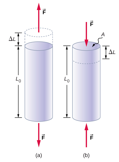
Tension or compression occurs when two antiparallel forces of equal magnitude act on an object along only one of its dimensions, in such a way that the object does not move. One way to envision such a situation is illustrated in Figure \(\PageIndex{1}\). A rod segment is either stretched or squeezed by a pair of forces acting along its length and perpendicular to its cross-section. The net effect of such forces is that the rod changes its length from the original length L0 that it had before the forces appeared, to a new length L that it has under the action of the forces. This change in length \(\Delta\)L = L − L0 may be either elongation (when \(L\) is larger than the original length \(L_o\)) or contraction (when L is smaller than the original length L0). Tensile stress and strain occur when the forces are stretching an object, causing its elongation, and the length change \(\Delta L\) is positive. Compressive stress and strain occur when the forces are contracting an object, causing its shortening, and the length change \(\Delta L\) is negative.
In either of these situations, we define stress as the ratio of the deforming force \(F_{\perp}\) to the cross-sectional area A of the object being deformed. The symbol F\(\perp\) that we reserve for the deforming force means that this force acts perpendicularly to the cross-section of the object. Forces that act parallel to the cross-section do not change the length of an object. The definition of the tensile stress is
\[tensile\; stress = \frac{F_{\perp}}{A} \ldotp \label{12.34}\]
Tensile strain is the measure of the deformation of an object under tensile stress and is defined as the fractional change of the object’s length when the object experiences tensile stress
\[tensile\; strain = \frac{\Delta L}{L_{0}} \ldotp \label{12.35}\]
Compressive stress and strain are defined by the same formulas, Equations \ref{12.34} and \ref{12.35}, respectively. The only difference from the tensile situation is that for compressive stress and strain, we take absolute values of the right-hand sides in Equation \ref{12.34} and \ref{12.35}.
Young’s modulus \(Y\) is the elastic modulus when deformation is caused by either tensile or compressive stress, and is defined by Equation \ref{12.33}. Dividing this equation by tensile strain, we obtain the expression for Young’s modulus:
\[Y = \frac{tensile\; stress}{tensile\; strain} = \frac{\frac{F_{\perp}}{A}}{\frac{\Delta L}{L_{0}}} = \frac{F_{\perp}}{A} = \frac{L_{0}}{\Delta L} \ldotp \label{12.36}\]
A sculpture weighing 10,000 N rests on a horizontal surface at the top of a 6.0-m-tall vertical pillar Figure \(\PageIndex{1}\). The pillar’s cross-sectional area is 0.20 m2 and it is made of granite with a mass density of 2700 kg/m3. Find the compressive stress at the cross-section located 3.0 m below the top of the pillar and the value of the compressive strain of the top 3.0-m segment of the pillar.

- Strategy
-
First we find the weight of the 3.0-m-long top section of the pillar. The normal force that acts on the cross-section located 3.0 m down from the top is the sum of the pillar’s weight and the sculpture’s weight. Once we have the normal force, we use Equation 12.34 to find the stress. To find the compressive strain, we find the value of Young’s modulus for granite in Table \(\PageIndex{1}\) and invert Equation \ref{12.36}.
- Solution
-
The volume of the pillar segment with height h = 3.0 m and cross-sectional area A = 0.20 m2 is
\[V = Ah = (0.20\; m^{2})(3.0\; m) = 0.60\; m^{3} \ldotp\]
With the density of granite \(\rho\) = 2.7 x 10³ kg/m3, the mass of the pillar segment is
\[m = \rho V = (2.7 \times 10^{3}\; kg/m^{3})(0.60\; m^{3}) = 1.60 \times 10^{3}\; kg \ldotp\]
The weight of the pillar segment is
\[w_{p} = mg = (1.60 \times 10^{3}\; kg)(9.80\; m/s^{2}) = 1.568 \times 10^{4}\; N \ldotp\]
The weight of the sculpture is ws = 1.0 x 10⁴ N, so the normal force on the cross-sectional surface located 3.0 m below the sculpture is
\[F_{\perp} = w_{p} + w_{s} = (1.568 + 1.0) \times 10^{4}\; N = 2.568 \times 10^{4}\; N \ldotp\]
Therefore, the stress is
\[stress = \frac{F_{\perp}}{A} = \frac{2.568 \times 10^{4}\; N}{0.20 m^{2}} = 1.284 \times 10^{5}\; Pa = 128.4\; kPa \ldotp\]
Young’s modulus for granite is Y = 4.5 x 10¹⁰ Pa = 4.5 x 10⁷ kPa. Therefore, the compressive strain at this position is
\[strain = \frac{stress}{Y} = \frac{128.4\; kPa}{4.5 \times 10^{7}\; kPa} = 2.85 \times 10^{-6} \ldotp\]
Significance
Notice that the normal force acting on the cross-sectional area of the pillar is not constant along its length, but varies from its smallest value at the top to its largest value at the bottom of the pillar. Thus, if the pillar has a uniform cross-sectional area along its length, the stress is largest at its base.
A 2.0-m-long steel rod has a cross-sectional area of 0.30 cm2. The rod is a part of a vertical support that holds a heavy 550-kg platform that hangs attached to the rod’s lower end. Ignoring the weight of the rod, what is the tensile stress in the rod and the elongation of the rod under the stress?
- Strategy
-
First we compute the tensile stress in the rod under the weight of the platform in accordance with Equation 12.34. Then we invert Equation 12.36 to find the rod’s elongation, using L0 = 2.0 m. From Table 12.1, Young’s modulus for steel is Y = 2.0 x 10¹¹ Pa.
- Solution
-
Substituting numerical values into the equations gives us
\[\begin{split} \frac{F_{\perp}}{A} & = \frac{(550\; kg)(9.8\; m/s^{2})}{3.0 \times 10^{-5}\; m^{2}} = 1.8 \times 10^{8}\; Pa \\ \Delta L & = \frac{F_{\perp}}{A} \frac{L_{0}}{Y} = (1.8 \times 10^{8}\; Pa) \left(\dfrac{2.0\; m}{2.0 \times 10^{11}\; Pa}\right) = 1.8 \times 10^{-3}\; m = 1.8\; mm \ldotp \end{split}\]
Significance
Similarly as in the example with the column, the tensile stress in this example is not uniform along the length of the rod. Unlike in the previous example, however, if the weight of the rod is taken into consideration, the stress in the rod is largest at the top and smallest at the bottom of the rod where the equipment is attached.
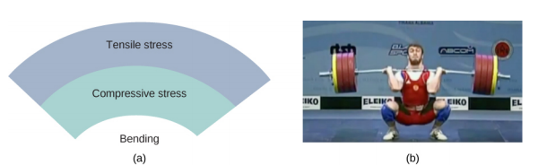
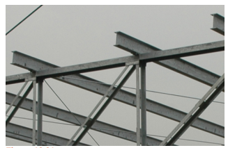
Objects can often experience both compressive stress and tensile stress simultaneously Figure \(\PageIndex{3}\). One example is a long shelf loaded with heavy books that sags between the end supports under the weight of the books. The top surface of the shelf is in compressive stress and the bottom surface of the shelf is in tensile stress. Similarly, long and heavy beams sag under their own weight. In modern building construction, such bending strains can be almost eliminated with the use of I-beams Figure \(\PageIndex{4}\).
We referred to the proportionality constant between stress and strain as the elastic modulus. But why do we call it that? What does it mean for an object to be elastic and how do we describe its behavior?
Elasticity is the tendency of solid objects and materials to return to their original shape after the external forces (load) causing a deformation are removed. An object is elastic when it comes back to its original size and shape when the load is no longer present. Physical reasons for elastic behavior vary among materials and depend on the microscopic structure of the material. For example, the elasticity of polymers and rubbers is caused by stretching polymer chains under an applied force. In contrast, the elasticity of metals is caused by resizing and reshaping the crystalline cells of the lattices (which are the material structures of metals) under the action of externally applied forces.
The two parameters that determine the elasticity of a material are its elastic modulus and its elastic limit. A high elastic modulus is typical for materials that are hard to deform; in other words, materials that require a high load to achieve a significant strain. An example is a steel band. A low elastic modulus is typical for materials that are easily deformed under a load; for example, a rubber band. If the stress under a load becomes too high, then when the load is removed, the material no longer comes back to its original shape and size, but relaxes to a different shape and size: The material becomes permanently deformed. The elastic limit is the stress value beyond which the material no longer behaves elastically but becomes permanently deformed.
Our perception of an elastic material depends on both its elastic limit and its elastic modulus. For example, all rubbers are characterized by a low elastic modulus and a high elastic limit; hence, it is easy to stretch them and the stretch is noticeably large. Among materials with identical elastic limits, the most elastic is the one with the lowest elastic modulus.
When the load increases from zero, the resulting stress is in direct proportion to strain in the way given by Equation 12.4.4, but only when stress does not exceed some limiting value. For stress values within this linear limit, we can describe elastic behavior in analogy with Hooke’s law for a spring. According to Hooke’s law, the stretch value of a spring under an applied force is directly proportional to the magnitude of the force. Conversely, the response force from the spring to an applied stretch is directly proportional to the stretch. In the same way, the deformation of a material under a load is directly proportional to the load, and, conversely, the resulting stress is directly proportional to strain. The linearity limit (or the proportionality limit) is the largest stress value beyond which stress is no longer proportional to strain. Beyond the linearity limit, the relation between stress and strain is no longer linear. When stress becomes larger than the linearity limit but still within the elasticity limit, behavior is still elastic, but the relation between stress and strain becomes nonlinear.
For stresses beyond the elastic limit, a material exhibits plastic behavior. This means the material deforms irreversibly and does not return to its original shape and size, even when the load is removed. When stress is gradually increased beyond the elastic limit, the material undergoes plastic deformation. Rubber-like materials show an increase in stress with the increasing strain, which means they become more difficult to stretch and, eventually, they reach a fracture point where they break. Ductile materials such as metals show a gradual decrease in stress with the increasing strain, which means they become easier to deform as stress-strain values approach the breaking point. Microscopic mechanisms responsible for plasticity of materials are different for different materials.
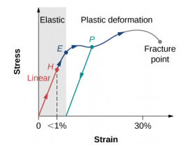
We can graph the relationship between stress and strain on a stress-strain diagram. Each material has its own characteristic strain-stress curve. A typical stress-strain diagram for a ductile metal under a load is shown in Figure \(\PageIndex{1}\). In this figure, strain is a fractional elongation (not drawn to scale). When the load is gradually increased, the linear behavior (red line) that starts at the no-load point (the origin) ends at the linearity limit at point H. For further load increases beyond point H, the stress-strain relation is nonlinear but still elastic. In the figure, this nonlinear region is seen between points H and E. Ever larger loads take the stress to the elasticity limit E, where elastic behavior ends and plastic deformation begins. Beyond the elasticity limit, when the load is removed, for example at P, the material relaxes to a new shape and size along the green line. This is to say that the material becomes permanently deformed and does not come back to its initial shape and size when stress becomes zero.
The material undergoes plastic deformation for loads large enough to cause stress to go beyond the elasticity limit at E. The material continues to be plastically deformed until the stress reaches the fracture point (breaking point). Beyond the fracture point, we no longer have one sample of material, so the diagram ends at the fracture point. For the completeness of this qualitative description, it should be said that the linear, elastic, and plasticity limits denote a range of values rather than one sharp point.
The value of stress at the fracture point is called breaking stress (or ultimate stress). Materials with similar elastic properties, such as two metals, may have very different breaking stresses. For example, ultimate stress for aluminum is 2.2 x 10⁸ Pa and for steel it may be as high as 20.0 x 10⁸ Pa, depending on the kind of steel. We can make a quick estimate, based on Equation 12.4.5, that for rods with a 1-in2 cross-sectional area, the breaking load for an aluminum rod is 3.2 x 10⁴ lb, and the breaking load for a steel rod is about nine times larger.
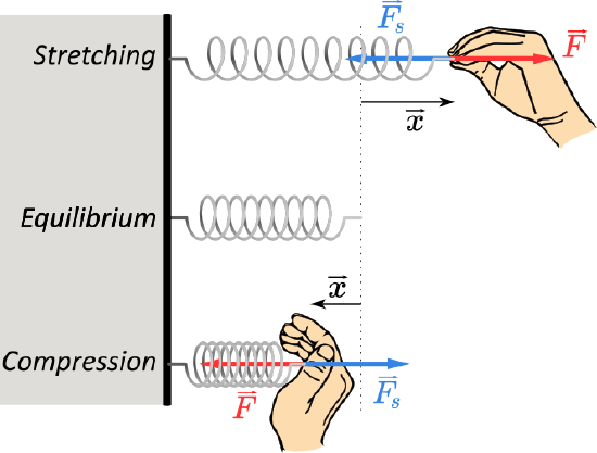
Spring force
A spring is a special medium with a specific atomic structure that has the ability to restore its shape, if deformed. To restore its shape, a spring exerts a restoring force that is proportional to and in the opposite direction in which it is stretched or compressed. This is the statement of a law known as Hooke’s law, which has the mathematical form
\[\vec{F} = -k \vec{x} \ldotp\nonumber \]
The constant of proportionality k is a measure of the spring’s stiffness. The line of action of this force is parallel to the spring axis, and the sense of the force is in the opposite direction of the displacement vector (Figure \(\PageIndex{9}\)). The displacement must be measured from the relaxed position; x = 0 when the spring is relaxed.