
3.3: Networks of Batteries and Resistors


- Last updated
- Aug 10, 2024
- Save as PDF

( \newcommand{\kernel}{\mathrm{null}\,}\)
Electromotive Force
We know that voltage differences drive electric currents through resistive materials, but where do these voltage differences come from? Up to now (with capacitors), we said that a voltage difference comes from a separated charge, but to separate that charge we need to move it, and if we do that with a voltage difference, we get into a vicious loop. We obviously need some influence other than a voltage difference due to separated charge in order to separate the charge in the first place. It turns out there are many such mechanisms, but we lump them all in to a general category known as electromotive force, or just emf. There is only one source of emf that we will look at in detail, and that won’t be for another couple chapters. For now, we are going to treat it as a black box, and call it a battery. Electromotive force has the effect of creating a voltage difference, so it has units of volts, but we will label it differently than say a voltage difference across a capacitor. We will use E.
The concept of emf is required primarily to explain what is going on in something called a circuit. A circuit is essentially a closed loop, where moving charge gets recycled. Let’s look at it from the perspective of a capacitor.
Figure 3.3.1a – Capacitor Drives a Current
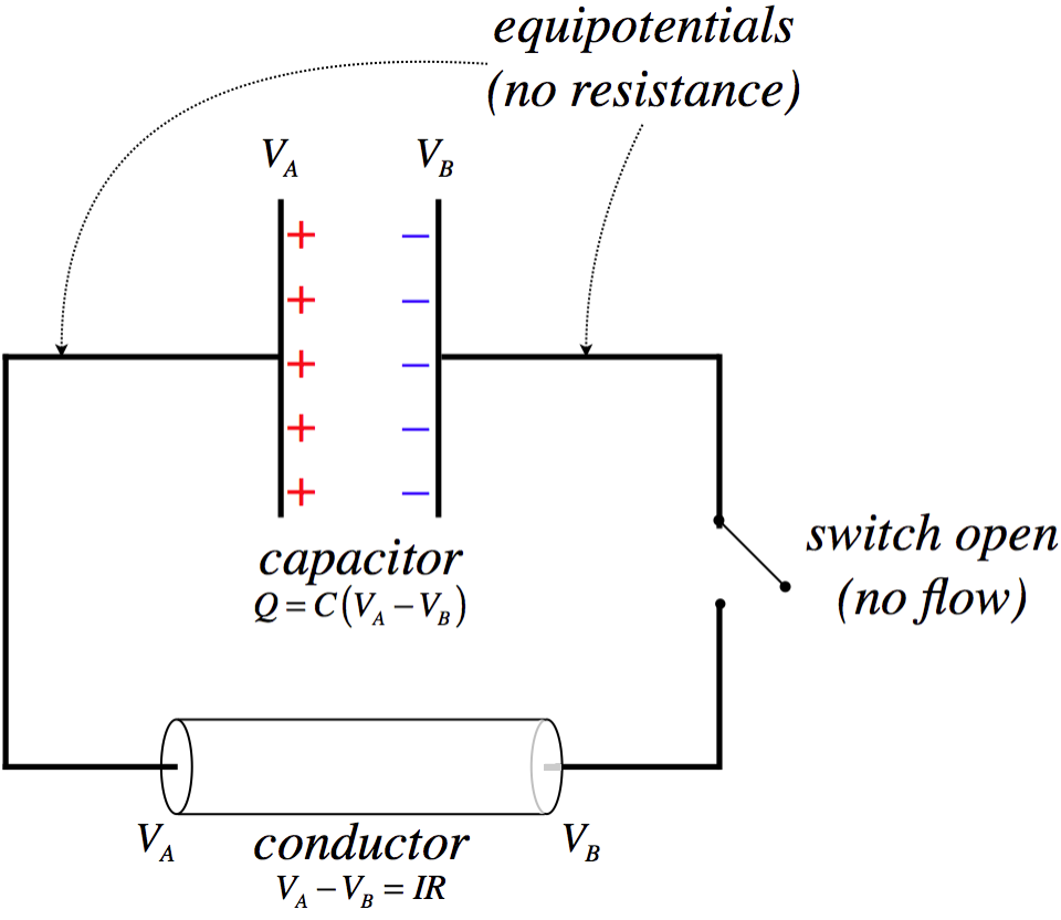
This figure is an abstraction of an actual circuit. In an actual circuit, there is a capacitor and some wires, along with a switch. Here we have collected all the resistive properties into a cylinder that we are calling the conductor. The lines that connect this to the capacitor are equipotentials (not wires!) that are introduced as a means for displaying the circuit. In any case, the separated charge on the capacitor comes with a potential difference across the plates, which then also (when the switch is closed) will become the same potential difference across the conductor.
Figure 3.3.1b – Capacitor Drives a Current
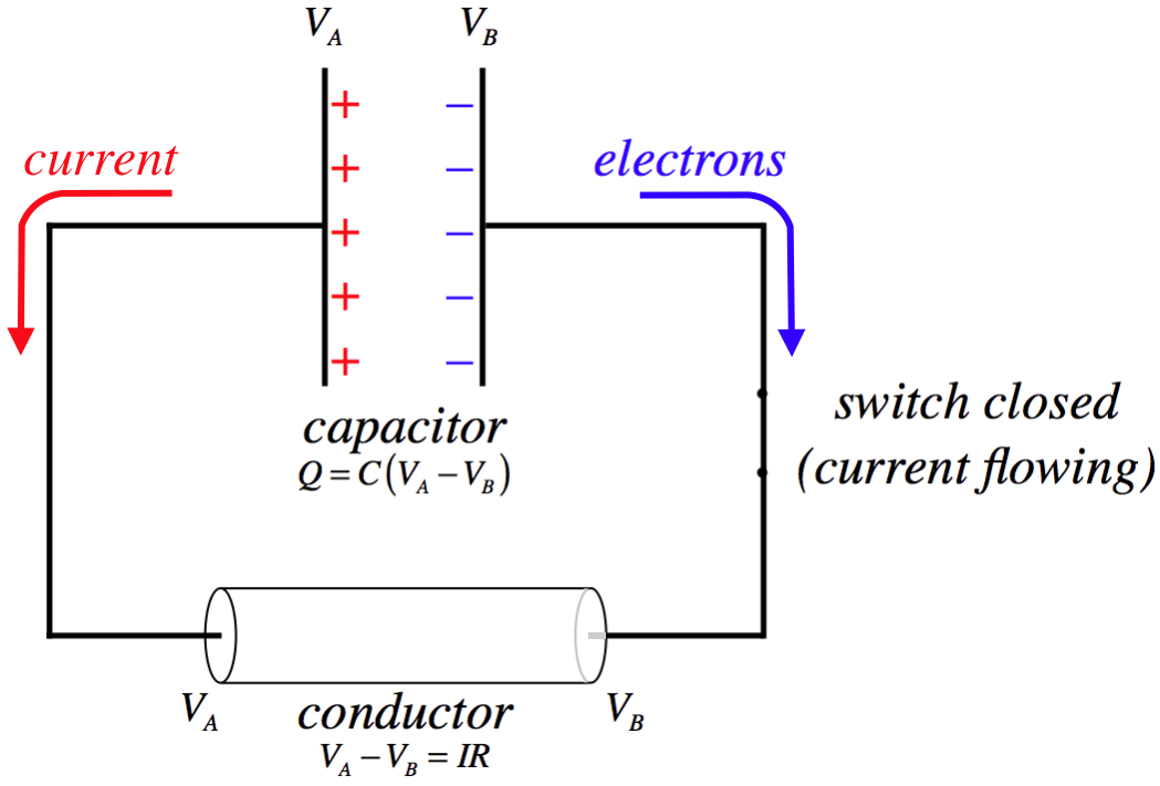
When the switch is closed, the potential difference due to the separated charge creates an electric field through the conductor, which exerts a force on the electrons, causing them to flow clockwise. Electric current is defined as the flow of positive charge, so it is defined to be in the opposite direction. The rate of flow is determined by the potential difference and the resistance. The resistance remains relatively constant, but what about the voltage difference?
Figure 3.3.1c – Capacitor Drives a Current
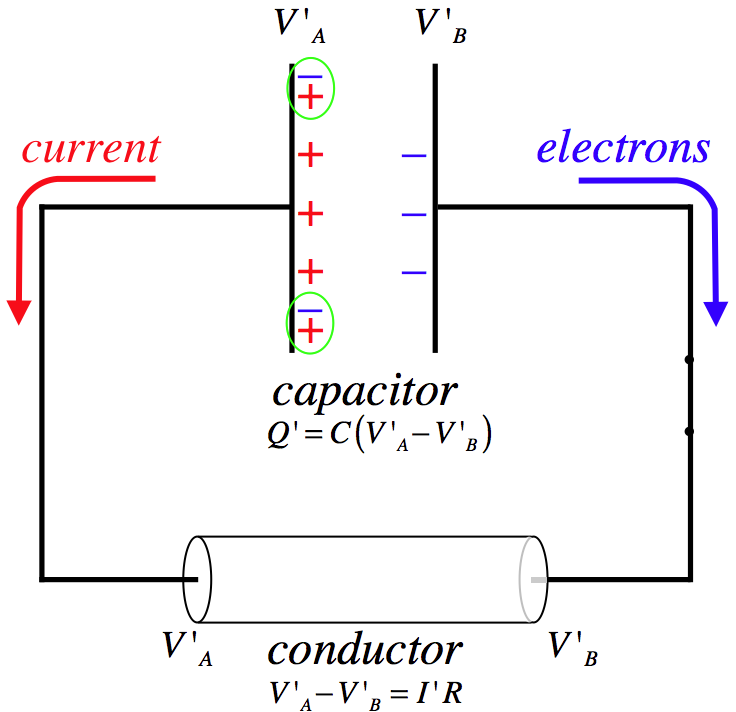
When electrons reach their destination on the positively-charged plate, they cancel some of the positive charge, thereby reducing the total charge on the capacitor. The capacitance doesn't change, so less charge corresponds to a smaller potential difference. A reduced potential difference yield a lower current through the conductor.
We are interested in maintaining a steady current through a conductor, and our definition of emf is such that it is that which maintains the potential difference so that the current can remain steady. So for example, if there existed magical "emf fairies" who, whenever an electron arrived on the positive plate, grabbed it and carried back to the negative plate, then they would be a source of emf.
Figure 3.3.2 – Electromotive Force Drives "Uphill" Charge Transportation
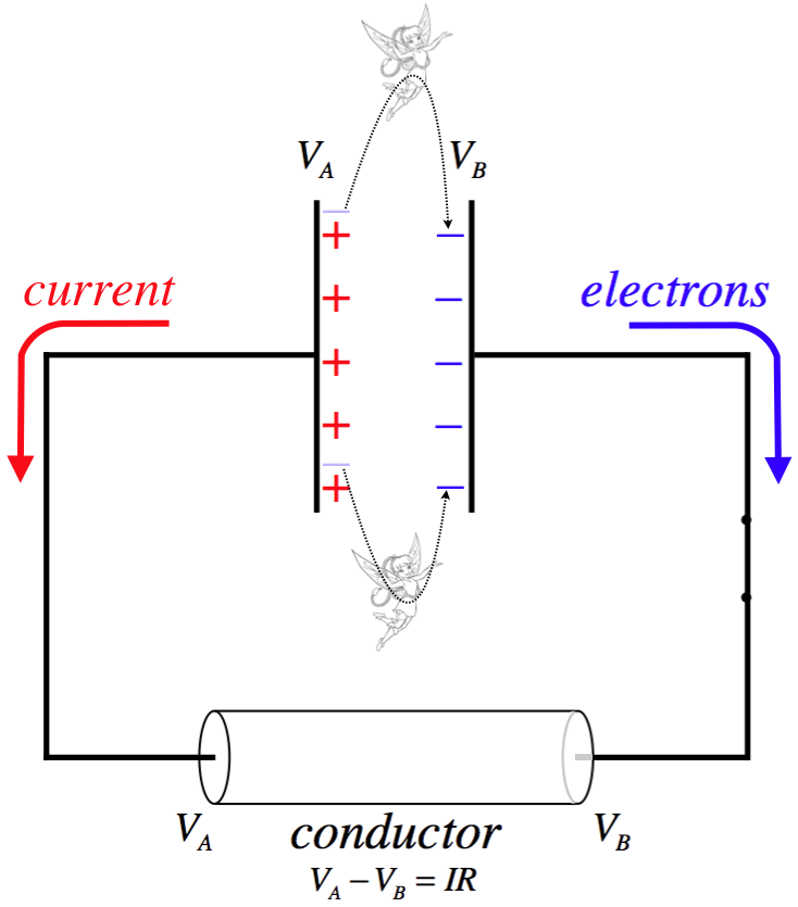
Naturally the transportation of charge back to where it started results in an increase of electrical potential energy in the system (to make up for what was converted to thermal when the current passed through the resistance), so the emf source must be drawing energy from elsewhere. In most real-world applications, we don't rely upon this energy source being the fairy world. Standard batteries convert chemical potential energy (released through chemical reactions) to drive this charge transportation. As stated earlier, we will see another means for doing this in a future chapter.
More Symbolic Diagrams
Now that we are discussing current flow, we need to add some more symbols to the collection we started in Section 2.6. In order to accommodate current flow, we now need a way to express resistance in symbolic form. This poses a bit of a problem, as resistance is ubiquitous – conducting wires that connect components to each other in a circuit, and the internal conducting parts contained in batteries, both exhibit resistance, for example.
resistance: 
There are electrical components called resistors whose sole purpose is to provide resistance to part of a circuit, but use of this symbol goes beyond that single application. For example, if one wants to incorporate the resistance present in a wire in a symbolic diagram, they will use straight lines (equipotentials) to specify where that wire is connected, and will also include one of these resistance symbols to indicate that this segment of wire comes with some resistance. The same is true with the case of internal resistance in a component like a battery – if the resistance in the battery is important, the battery is represented in the symbolic diagram in two parts: The usual battery symbol to cover the emf it provides, and a separate resistance symbol to account for the battery's internal resistance. Very often the resistance in a wire or a battery is negligible compared to components in the circuit, and in these cases it's okay to approximate the resistance of the wire as zero, and representing wires with straight lines is acceptable.
In our discussion of static networks of capacitors, we didn't talk about how quantities like charge and potential difference are measured. While we won't go into the inner workings of measuring devices used in electrical circuits, it will be useful to introduce symbols for them.
voltmeter: 
This device measures the voltage difference between the equipotentials on either side of it. This device can be used as a "external probe" by connecting the two equipotentials protruding from it to any two places in a circuit, and the meter will show the voltage difference between these two points. This probe is "external" because it can be used without disturbing the circuit in any way.
This meter will also provide the information regarding which of the two equipotentials is at the higher potential. So for example, if one connects a voltmeter leads to the opposite sides of a battery, then it will read the voltage of the battery and which side of the battery is at the higher potential. This device has what is effectively an infinite resistance, so that the circuit can be probed without affecting what is going on in the circuit, since none of the current flow will flow through the voltmeter when it is attached.
ammeter: 
This device measures the amount of current that flows through it, including the direction in which the current is flowing. Unlike the voltmeter, this device cannot be connected to two points in a circuit as an external probe, but rather functions as an "internal probe." In order to measure the current through a component, one of the wires connecting that component must be disconnected from the circuit, and the ammeter inserted between the component and the rest of the circuit where there was previously only the wire. In order to not affect what is actually happening in the circuit, this device must essentially behave like an equipotential, which means it must have effectively zero resistance.
Systems of Resistors
When we combined capacitors in a circuit, we found a way to put them together into equivalent capacitances depending upon whether they were connected in series or parallel. We can do the same with resistors. The definitions of parallel and series are the same as before, because the same principles of equipotentials and charge conservation still hold.
Figure 3.3.3 – Resistors in Series
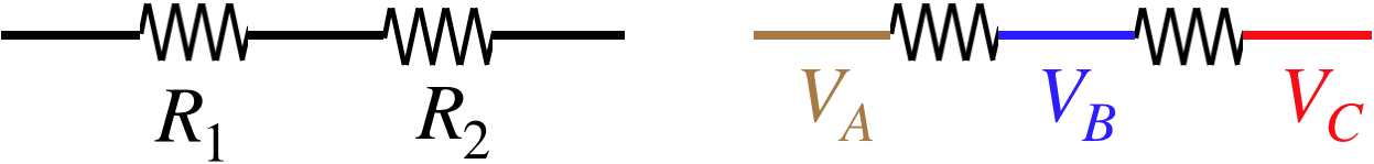
The voltage drop across resistor R1 is VA−VB, and across R2 is VB−VC so as with the case of the series capacitors, the sum of the individual voltage drops equals the total voltage drop across both resistors combined:
Vtot=V1+V2
Also, we insist that no net charge builds up within, or is lost from, the resistors, so whatever current enters resistor R1 must also exit it, and then enter resistor R2 (and then exit it), so the current through the combination equals the current through each individual component:
Itot=I1=I2
Figure 3.3.4 – Resistors in Parallel
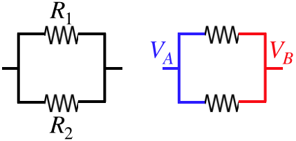
The voltage drops across the resistors are the same:
V1=VA−VB=V2
Whatever current is entering one side of the combination must leave the right side, and must be divided between the two branches it can follow:
Itot=I1+I2
Given that all of the rules for voltage drops and disposition of charge are the same for capacitors and resistors, we can jump straight to the answers for equivalent resistance. To do this, however, we have to note that Ohm's law is slightly different from the definition of capacitance. If we make the association of charge with current, we get an inverse parallel between capacitance and resistance:
V=Q1CV=IR}⇒1C↔R
So we can recycle the equivalence equations found for capacitance if we just replace C with 1R:
Vtot=IReqV1=IR1V2=IR2Vtot=V1+V2}Req=R1+R2(series)
Itot=VReqI1=VR1I2=VR2Itot=I1+I2}1Req=1R1+1R2(parallel)
Internal Resistance
Consider the following puzzle: If we connect a single resistor to a real battery and measure the voltage drop across it with a voltmeter we find it to be 6.1V. Then we double the number of resistors, and repeat the voltmeter measurement, and much to our surprise, find that the voltage drop is a little bit higher: 6.2V. How can this be?
Real batteries contain real conductors, and therefore exhibit their own bit of resistance. We refer to this as the internal resistance of the battery, and the resistance outside the battery is known as the load.
Figure 3.3.5 – Effect of Load on a Real Battery
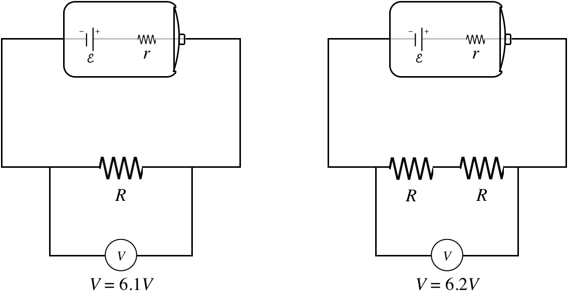
The math works out like this… First find the equivalent resistance of each circuit, and use it to determine the current that flows through it:
smaller load:Req=R+r⇒I=ER+rlarger load:Req=2R+r⇒I=E2R+r
So there is a different current flowing through each load, and combining these different currents with the different total resistance yields a slightly different voltage drop for each:
smaller load:V=IR=(ER+r)R=(RR+r)E=6.1Vlarger load:V=I(2R)=(E2R+r)(2R)=(2R2R+r)E=6.2V
The bigger the load is in comparison to the internal resistance, the closer the voltage measured across the load gets to equaling the emf supplied by the battery, because the impact of the r in the denominator on the overall calculation is diminished.
Note that when we draw a diagram, the little symbol is for emf, not for a real battery. If a real battery is intended, then either a battery appears in the picture, or the internal resistance is represented by a symbol for a resistor. The potential difference measured across the two battery leads (or “terminals”) is called the terminal voltage, and is less than the emf by an amount equal to the voltage drop caused by the internal resistance. The terminal voltage clearly varies according to load, because the amount of current passing through the internal resistance varies according to load and the emf is fixed.
Example 3.3.1
When the switch in the circuit shown in the diagram is open, the voltmeter reads 6.09V. When the switch is closed, the voltmeter reading drops to 5.92V, and the ammeter reads 1.44A.
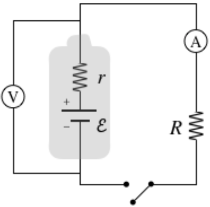
- Find what the ammeter reads before the switch is closed.
- Find the internal resistance r and emf E of the battery.
- Find the resistance R of the load.
- Solution
-
a. With the switch open, there is no potential difference across the load, so there is no current flowing through it. The load is in series with the ammeter, so if there is no current through the resistor, there is also no current through the ammeter.
b. When the switch is open, no current is flowing at all (we assume the voltmeter is ideal, so it has infinite resistance and no current will flow through it), so there is no voltage drop across the internal resistance. Therefore the voltmeter reads the emf of the battery when the switch is open:
E=6.09V
When the circuit is closed, the ammeter reads a current of 1.44A passing through the resistor, and since the ammeter is in series with the battery, this is the current flowing through the battery’s internal resistance. The potential change measured by the voltmeter in this case is the emf supplied by the battery minus the voltage drop of the internal resistance, so:
E−Ir=ΔV⇒r=E−ΔVI=6.09V−5.92V1.44A=0.118Ω
c. The voltmeter also measures the voltage drop across the load, so with the measured current, we get the resistance:
R=ΔVI=5.92V1.44A=4.11Ω
Fuses and Circuit Breakers
In general we prefer not to dissipate too much energy in the internal resistance of a battery. All this does is warm the battery, and the energy that could be used to make a toy function is lost to the environment as thermal energy. As we will see a bit later, the emf we get from our wall sockets is not coming from a battery, and therefore doesn’t have an issue with internal resistance. The only systemic resistance present is the resistance in the wires themselves. This turns out to be a double-edged sword.
Electrical devices that we plug in are designed to function at a specific voltage, namely the voltage difference provided by our outlets (110V). If we want to use two devices at once (say the TV and the DVR), then we can’t plug these in series, or they would each get less than 110 volts. We therefore connect them in parallel. Let’s suppose we want to plug in many such devices at once (into the same outlet). What happens to the total current drawn from the outlet? Well, the equivalent resistance goes down as we add more devices in parallel, making the total current go up. Now consider what happens to the power dissipated by the wires in the house. The resistance in these wires is small, so when we add enough devices the lower limit on resistance is very small, making the upper limit on current very large. With lots of current passing through the house wires, they get very hot. This is obviously a safety problem. How do we prevent houses from bursting into flames when we plug in too many devices?
The trick is to put a controlled weak link into the wiring. In the old days, this consisted of devices called fuses. A fuse consisted of a thin, wispy little wire, enclosed safely within a small module that screwed into a "fuse box" that connected into the wiring somewhere in the house. Because the wire within a fuse was so thin, it would melt when the current got to be too high, thereby breaking the circuit. The amount of current needed to melt this weak link was significantly less than the current needed to cause a fire through the wiring in the walls.
Fuses are still used in individual devices, but you don’t really see them in houses anymore. Good thing, too: Home owners who had faulty wiring got tired of constantly buying and replacing fuses, and discovered that they could “solve” the problem by placing a penny (which coincidentally had about the same diameter as fuses) in place of the fuse. Of course, a penny is not a very weak link, and many fires resulted from this dangerous practice.
Nowadays we use devices known as “circuit breakers” in place of fuses. One basic design for a circuit breaker looks like this:
Figure 3.3.6 – Design of a Circuit Breaker
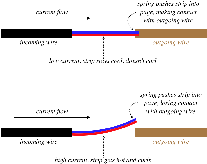
The working parts of this device consist of a bimetallic strip (see the end of Section 5.2 of the Physics 9B LibreText for details on this ingenious device), and a spring. The figure above shows a top view of the circuit breaker, and the spring pushes down on the right end of the bimetallic strip. When the current is low, the temperature of the strip remains low, and it doesn't curl, so the spring pushes the strip into the outgoing wire, making the connection. But when the strip gets too hot, it curls past the outgoing wire, breaking the connection, and the spring pushes the strip so that the connection is not reestablished when the strip cools again (otherwise the electricity through that circuit would surge on-and-off intermittently). Then when the excessive load is removed, the spring is physically compressed, putting the strip back into place. Unlike a fuse, this device can be used over and over.