5.7: Thermodynamic Processes
( \newcommand{\kernel}{\mathrm{null}\,}\)
Definition of a Thermodynamic Process
Up to now, we haven't spent a lot of time on the dynamics part of thermodynamics. So far our notion of dynamics has been limited to talking about heat transfer, and how it relates to temperature change. Indeed, in Section 5.5 we concluded that we can only really deal with equilibrium states, which seems to directly contradict the notion of examining dynamics, which requires changes in the state.
We get around this apparent conundrum through the introduction of something called a quasi-static process. The idea is that a system can evolve from one equilibrium state to a neighboring one (i.e. one infinitesimally close) slowly, so that at any instant in time the state variables are in perfect balance are are not "leaning" toward change. A nice analogy for this idea of a quasi-static process is someone balancing on a large ball. When they are balanced, they are in equilibrium. But they would like to move the ball along, so they move their feet ever so slightly, and the ball rolls a tiny bit. The ball stops, and the person is again in equilibrium. They can continue this process to get across the floor, inching from one equilibrium state to another, never endangering themselves. Alternatively, they could just “go for it” and start moving their feet fast. In this case, they will have to lean, and cannot simply stop whenever they like at an equilibrium position. The slow, equilibrium-to-equilibrium process is what we call quasi-static.
Another aspect of processes that we need to define is reversibility. A process is reversible if it needs to be "coaxed" into occurring – if the process occurs spontaneously from the initial conditions, then it is said to be irreversible. It's certainly true that if a process is not quasi-static, then it is irreversible – the person that is off-balance on the ball has no ability to stop the ball or reverse its direction at any instant, so the system evolves from a given state without coaxing. So a process being quasi-static is necessary for it to be reversible, but it is not sufficient.
To see this, suppose we have a large imbalance between two adjacent systems. For example, one system may be significantly hotter than the other. If these are put into direct contact, then the heat will transfer very fast – not quasi-statically – and since this process proceeds spontaneously, it is irreversible. But now suppose we introduce a transfer conduit to conduct the heat between the two systems. The thermal conductivity of the conduit medium (and/or the length of the conduit) can be made arbitrarily-small, slowing the heat transfer process to a trickle into the colder system. This would be a quasi-static process, because at any moment if we cut off the transfer (insert insulation), the systems don't have to "settle into" equilibrium – they are already there, because the changes have been so slow. However, if we again remove the insulation, these systems do not remain in the same state – they spontaneously start evolving (albeit slowly) again. They are not equally-likely to go in either direction – the heat spontaneously transfers from hot to cold. We will discuss this idea of reversibility further in future sections.
Process Diagrams
One way to analyze processes is with process diagrams, which are depictions (graphs) of processes through equilibrium states. We already said that in general, equations of state involve four state variables (one state variable dependent upon three others), so if we want to graph general processes, we will need many dimensions. We will not be dealing with processes during which the particle number changes, so all of our diagrams hold that number fixed. That leaves three variables with two of them independent, and the third being derived from the other two through the equation of state. The two independent variables that we choose can be plotted on a pair of axes, and the point thus plotted will represent a specific thermodynamic state. As we must use absolute temperature, none of the state variables (such as pressure, volume, and internal energy) can ever be negative, so these plots only require one quadrant of the axes.
Figure 5.7.1 – Equilibrium Thermodynamic States Plotted on Two Axes
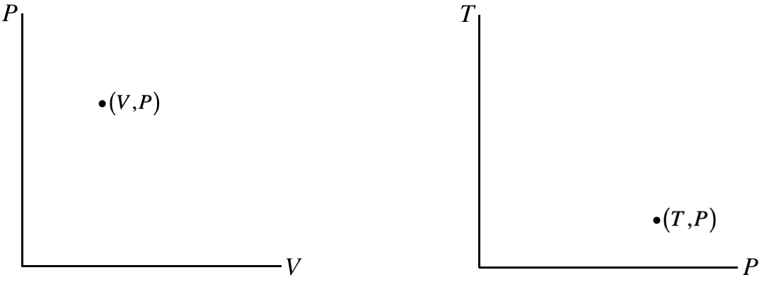
The points on these diagrams, in conjunction with separate information about the number of particles and an equation of state (like PV=nRT) completely define an equilibrium state (i.e. the values of all of the state variables) of the system.
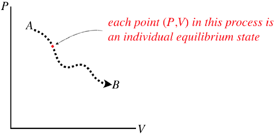
A quasi-static process would be represented on one of these diagrams as a continuous curve (along with an indicated direction), because in such a process a system changes from one equilibrium state to another that is infinitesimally close. If we want to know what state the system is in at any point during a process, we just read off that point’s values. The process does not have any “momentum,” meaning that if we stop it at any point, it is not inclined to continue to the next point – it is an equilibrium state.
Figure 5.7.2 – Every Point on a Process Diagram is an Equilibrium State
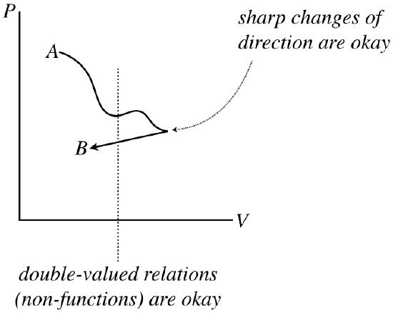
Note that these processes are not necessarily functions – it is perfectly acceptable for a process to circle back on itself. They also don’t need to be differentiable (smooth), because each state along the way has no memory of the state that comes before, or anticipation of the state that follows.
Figure 5.7.3 – Process Diagrams Do Not Need to be Differentiable Functions
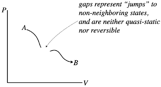
However, the graph of the process does need to be continuous. Sudden jumps represent states suddenly changing to other states that are not nearby, which can only be achieved by going through a non-equilibrium state – such a process is not quasi-static. Another way to think of this is in terms of reversibility. Gaps involve jumps between states, and without any “bread crumbs,” showing the system the way back, there is no way to retrace steps, and the process is therefore not reversible.
Figure 5.7.4 – Process Diagrams Must be Continuous to be Quasi-Static
Work Done By a Gas
We said earlier that the two “oddballs” in the field of thermodynamics are heat and work, and we’ve talked a bit about heat, so it’s time we explore the topic of work a bit more. We already know something about it from Physics 9A:
W(A→B)=B∫A→F⋅→dl=B∫A|→F||→dl|cosθ
How does this apply to our study of the thermodynamics of ideal gases? Well, gases exhibit pressure, which can result in the exertion of a force, so all we need to do is conceive of a case where gas pressure moves something. To this end, consider a gas confined by a container with a piston:
Figure 5.7.5 – Work Done on a Piston by a Confined Gas
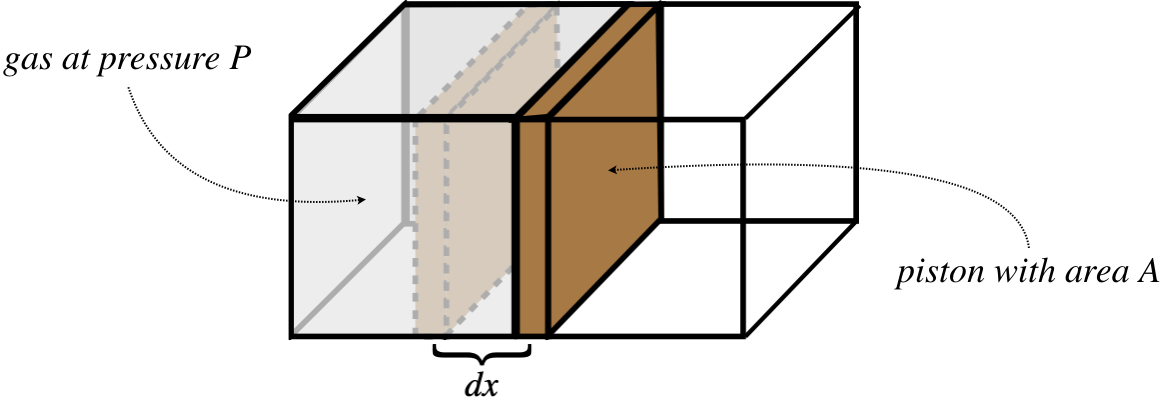
The confined gas exerts a force on the piston that equals the pressure of the gas multiplied by the area of the piston. The forces acts to push the piston outward a small distance, thereby doing a small amount of work on it, giving:
dWbygas=Fdx=PAdx
But the product Adx equals the small change in the gas's volume dV, allowing us to write the work done in terms of two state variables. As along as the piston expands slowly, the gas will go from one equilibrium state to another in a quasi-static manner, giving a total amount of work equal to:
Wbygas=B∫APdV
In terms of the process diagram of pressure vs. volume, this integral is simply the area under the curve.
Figure 5.7.6 – Work Done by Gas is Area Under PV Curve
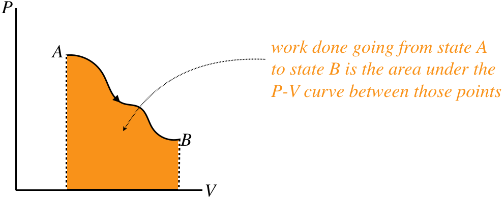
Notice that the sign of the work is also important. If the gas is compressed rather than expanded, then the process goes right-to-left in the PV diagram, and the integral is negative. We therefore assert the following sign convention:
work done by an expanding gas has a (+) sign, while work done on a gas to compress it has a (–) sign
For comparison purposes, let's restate the sign convention for heat transfer:
heat transferred into a gas has a (+) sign, while heat transferred out of a gas has a (–) sign
The First Law of Thermodynamics
Now that we have placed work and heat into the big picture of thermodynamics, we can apply a principle we have known since early in Physics 9A. We do this by taking an accounting of all the energy associated with a thermodynamic system. We know that all of the energy within the system (all kinetic and potential energy) is accounted-for in the internal energy U, which is a state function. Work and heat both either bring energy into or take energy away from the system. According to the law of conservation of energy, whatever the net result of the energy transfer is must be reflected in the change of internal energy. Since work is done by the gas, a positive amount of work done is energy that comes out of the gas, while a positive amount of heat is energy that enters the gas. The change in the gas's internal energy is positive when net energy comes in and negative when net energy exits, so it is given by:
ΔU=Q−W
This simple expression of energy conservation is known as the first law of thermodynamics.
Alert
Chemistry and physics classes typically approach the sign conventions for the first law differently. The symbol W in the equation above represents the work done by the gas. Chemists generally use the symbol W to represent the work done on the gas, which has the effect of changing the sign of W in the equation for the first law. Obviously the physical meaning is the same in both cases, but the choice in sign convention likely comes from a difference in emphasis. The convention from chemistry has the advantage of symmetry between the sign conventions for heat and work (both are positive when energy is going into the gas). Also, chemists are more likely to concern themselves with the effects of work on a gas than the effects of gas on its surroundings. One advantage to the sign convention used here is that the work integral in terms of pressure and volume doesn't require a negative sign – the work done by a gas is more intuitive than the work done on it. Another is that we will be discussing engines, which have the role of converting heat taken in into work put out. The "physics sign convention" is more convenient for a process where the amount of heat in equals the amount of work out. Anyone who finds these differences in sign conventions confusing should just always think "work done by the gas" when they see W in the formulas encountered in this text.
As simple as this law is (after all, it is just conservation of energy), it has some interesting properties. The most striking is that we have a change in a state variable (U) on one side of the equation (which depends only upon the starting and ending states of the process), while on the other side are two quantities that depend upon the path taken. This tells us that different paths between two states result in different amounts of each type of energy transfer, but the final energy change is the same, as it only depends upon the endpoints.
Example 5.7.1
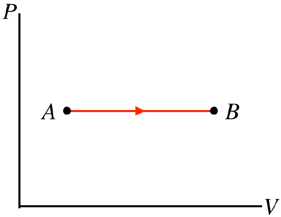
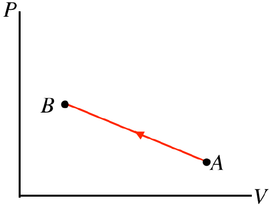
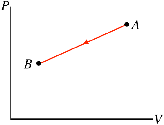
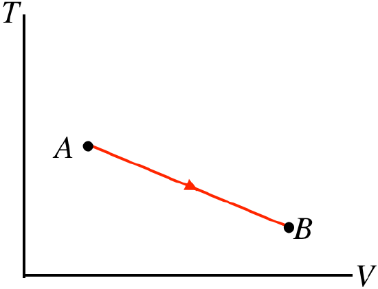
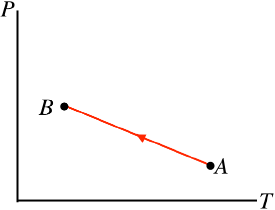
For each of the straight-line processes for an ideal gas shown below, answer the following questions:
- Work done: on the gas, by the gas, or can't tell?
- Heat transferred: into the gas, out of the gas, or can't tell?
- Temperature change: gas gets hotter, gas gets colder, or can't tell?
- Solution
-
For all of these graphs, we have the following tools to work with:
PV=nRTU=nCVTW=B∫APdVΔU=Q−W
a. The process goes from left to right, so the positive work is done by the gas. The pressure doesn't change during this process, but the volume goes up, so the quantity PV must increase from A to B. With the number of moles not changing, the ideal gas law tells us that the temperature must go up. The increase in temperature means that the internal energy goes up, or ΔU>0. We already said that W>0, so from the first law we find that Q>0, which means that heat enters the gas.
b. The process goes from right to left, so the work done by the gas is negative, which means work is done on the gas. With the pressure rising and the volume falling, there is no way to tell what happens to the temperature without more details of the endpoints. Without knowing whether the temperature goes up or down, there's no way to tell what happens to the internal energy, which gives us no way to use the first law to determine whether heat is entering or leaving the system.
c. Right-to-left process → work done on gas. Both the pressure and the volume go down, which means that PV goes down, allowing us to use the ideal gas law to conclude that the temperature also goes down. The decrease in temperature means ΔU<0, and since W<0, the first law requires that Q<0, so heat leaves the system during this process.
d. Note that this is process expressed in terms of temperature vs. volume. The area under this curve does not give us the work done! Though we don't know what happens to the pressure during this process, the volume nevertheless increases, which means that the gas is expanding and pushing a piston outward, so positive work is done. The temperature (measured on the vertical axis) clearly drops during the process. We know that W>0 and ΔU<0, so the first law can't tell us what happens with the heat without more details about the endpoints A and B.
e. This process is expressed in terms of pressure and temperature. It isn't immediately clear from the graph whether the volume is expanding or not, so we will have to wait on drawing a conclusion about work. The temperature (measured on the horizontal axis) is dropping because the process is right-to-left. The pressure is rising while this occurs, so from the ideal gas law, the volume must get smaller during this process. When the volume gets smaller, the gas is compressed, so work is done on the gas. With U<0 (temperature drops) and W<0 (volume decreases), the first law tells us that Q<0, so heat is leaving the system.
Example 5.7.2
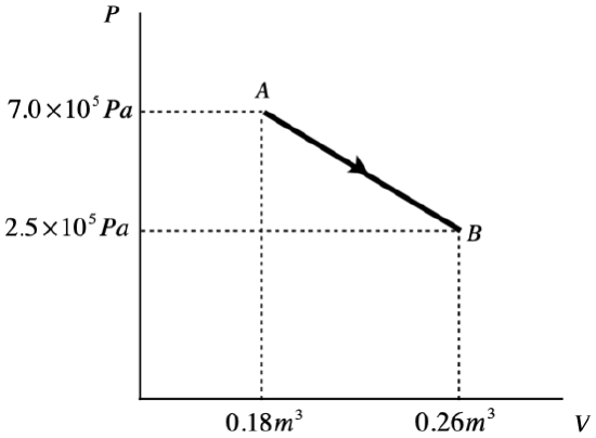
A monatomic ideal gas undergoes a quasi-static process from state A to state B, illustrated in the PV diagram below. The process forms a straight line on the P-vs-V graph.
- Calculate the work done in this process.
- Find the change in internal energy from state A to state B.
- Find the quantity of heat transferred into or out of the system during this process and indicate whether the heat goes in or comes out.
- Solution
-
a. The work done during a process is the area under the P-vs-V curve, so all we need to do is compute the area of the top triangle and the bottom rectangle and add them:
toptrianglearea=12bh=12ΔPΔV=1.8×10⁴Jbottomrectanglearea=PminΔV=2.0×10⁴J}⇒W=3.8×10⁴J
b. The gas is monatomic, so the change in internal energy is:
ΔU=32nRΔT=32(nRTB−nRTA)
Putting in the ideal gas law gives:
ΔU=32(PBVB−PAVA)=−9.2×10⁴J
c. The amount of heat transferred comes directly from the first law of thermodynamics:
ΔU=Q−W⇒Q=ΔU+W=−9.2×10⁴J+3.8×10⁴J=−5.4×10⁴J
The negative sign indicates that this heat is lost by the system. Given that work is also done by the gas (work is positive), it isn't surprising that the internal energy goes down (and with it the temperature of the gas).
Quasi-Static vs. Non-Quasi-Static Processes
We know that work and heat only represent exchanges of energy, or changes to a system – they are not values stored in the state of a system. This means that a single point on a process diagram does not define an amount of work or heat (in the case of work, you cannot define an area under a point!). In fact it turns out that every time a process occurs, it occurs because of either an exchange of heat or work or both. Instead of thinking of heat and work exchange as a result of a process, we can think of them as the cause of a process.
Alert
Note that it is possible to change states without doing work, but in that case heat must be transferred, and it is possible to change states without heat being transferred, but in that case work must be done.
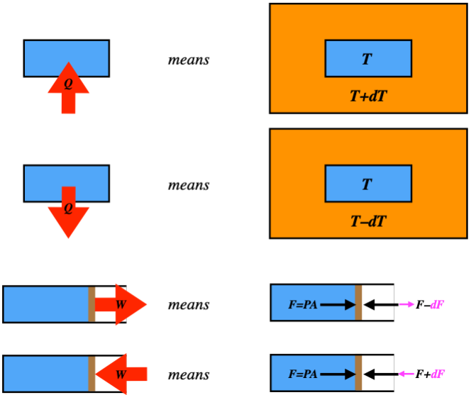
Let’s start with a piston at equilibrium, so the force on it due to the pressure of the gas is exactly balanced by a force pushing inward from the outside, holding it in place. Suppose we drop the force from the outside by a few Newtons – what happens? The piston expands outward until the pressure drops enough to rebalance the forces. The force imbalance causes the piston to accelerate. On its way to its final position, it is not in equilibrium, so this process is not quasi-static! We can’t figure out the work, because the pressure of the non-equilibrium gas is not well-defined. Furthermore, the piston gains some kinetic energy, so some of the work goes into that. It’s a total mess. This all came about because we didn’t control the process from one equilibrium state to the next. This control is only achievable if the work is done incrementally. That is, any finite difference in forces on the piston causes the process to be non-quasi-static, but if we do just infinitesimal changes in the force, we are okay. Of course, this is not something we can do in practice, but it turns out that doing this kind of analysis is worthwhile nonetheless. For now it is important to understand that such a non-quasi-static process comes from a finite imbalance in the force.
It turns out that the same is true for heat. Recall that heat is the transfer of energy due to a temperature difference (analogous to the force difference for work). A process that involves heat transfer is only quasi-static if it occurs due to an infinitesimal temperature difference. Again, this is not something we can manage in the real world – we usually just put a hot system next to a cold one – but it is useful to use this analysis in the same way that it is useful to study frictionless motion in mechanics.
We will be drawing lots of diagrams that indicate work done and heat transferred, and since we are always assuming quasi-static processes, it is important to have a clear picture of what these diagrams are depicting.
Figure 5.7.7 – Interpreting Heat and Work Exchanges in Diagrams
