
2.8.5: Total internal reflection
- Page ID
- 138915
\( \newcommand{\vecs}[1]{\overset { \scriptstyle \rightharpoonup} {\mathbf{#1}} } \)
\( \newcommand{\vecd}[1]{\overset{-\!-\!\rightharpoonup}{\vphantom{a}\smash {#1}}} \)
\( \newcommand{\dsum}{\displaystyle\sum\limits} \)
\( \newcommand{\dint}{\displaystyle\int\limits} \)
\( \newcommand{\dlim}{\displaystyle\lim\limits} \)
\( \newcommand{\id}{\mathrm{id}}\) \( \newcommand{\Span}{\mathrm{span}}\)
( \newcommand{\kernel}{\mathrm{null}\,}\) \( \newcommand{\range}{\mathrm{range}\,}\)
\( \newcommand{\RealPart}{\mathrm{Re}}\) \( \newcommand{\ImaginaryPart}{\mathrm{Im}}\)
\( \newcommand{\Argument}{\mathrm{Arg}}\) \( \newcommand{\norm}[1]{\| #1 \|}\)
\( \newcommand{\inner}[2]{\langle #1, #2 \rangle}\)
\( \newcommand{\Span}{\mathrm{span}}\)
\( \newcommand{\id}{\mathrm{id}}\)
\( \newcommand{\Span}{\mathrm{span}}\)
\( \newcommand{\kernel}{\mathrm{null}\,}\)
\( \newcommand{\range}{\mathrm{range}\,}\)
\( \newcommand{\RealPart}{\mathrm{Re}}\)
\( \newcommand{\ImaginaryPart}{\mathrm{Im}}\)
\( \newcommand{\Argument}{\mathrm{Arg}}\)
\( \newcommand{\norm}[1]{\| #1 \|}\)
\( \newcommand{\inner}[2]{\langle #1, #2 \rangle}\)
\( \newcommand{\Span}{\mathrm{span}}\) \( \newcommand{\AA}{\unicode[.8,0]{x212B}}\)
\( \newcommand{\vectorA}[1]{\vec{#1}} % arrow\)
\( \newcommand{\vectorAt}[1]{\vec{\text{#1}}} % arrow\)
\( \newcommand{\vectorB}[1]{\overset { \scriptstyle \rightharpoonup} {\mathbf{#1}} } \)
\( \newcommand{\vectorC}[1]{\textbf{#1}} \)
\( \newcommand{\vectorD}[1]{\overrightarrow{#1}} \)
\( \newcommand{\vectorDt}[1]{\overrightarrow{\text{#1}}} \)
\( \newcommand{\vectE}[1]{\overset{-\!-\!\rightharpoonup}{\vphantom{a}\smash{\mathbf {#1}}}} \)
\( \newcommand{\vecs}[1]{\overset { \scriptstyle \rightharpoonup} {\mathbf{#1}} } \)
\(\newcommand{\longvect}{\overrightarrow}\)
\( \newcommand{\vecd}[1]{\overset{-\!-\!\rightharpoonup}{\vphantom{a}\smash {#1}}} \)
\(\newcommand{\avec}{\mathbf a}\) \(\newcommand{\bvec}{\mathbf b}\) \(\newcommand{\cvec}{\mathbf c}\) \(\newcommand{\dvec}{\mathbf d}\) \(\newcommand{\dtil}{\widetilde{\mathbf d}}\) \(\newcommand{\evec}{\mathbf e}\) \(\newcommand{\fvec}{\mathbf f}\) \(\newcommand{\nvec}{\mathbf n}\) \(\newcommand{\pvec}{\mathbf p}\) \(\newcommand{\qvec}{\mathbf q}\) \(\newcommand{\svec}{\mathbf s}\) \(\newcommand{\tvec}{\mathbf t}\) \(\newcommand{\uvec}{\mathbf u}\) \(\newcommand{\vvec}{\mathbf v}\) \(\newcommand{\wvec}{\mathbf w}\) \(\newcommand{\xvec}{\mathbf x}\) \(\newcommand{\yvec}{\mathbf y}\) \(\newcommand{\zvec}{\mathbf z}\) \(\newcommand{\rvec}{\mathbf r}\) \(\newcommand{\mvec}{\mathbf m}\) \(\newcommand{\zerovec}{\mathbf 0}\) \(\newcommand{\onevec}{\mathbf 1}\) \(\newcommand{\real}{\mathbb R}\) \(\newcommand{\twovec}[2]{\left[\begin{array}{r}#1 \\ #2 \end{array}\right]}\) \(\newcommand{\ctwovec}[2]{\left[\begin{array}{c}#1 \\ #2 \end{array}\right]}\) \(\newcommand{\threevec}[3]{\left[\begin{array}{r}#1 \\ #2 \\ #3 \end{array}\right]}\) \(\newcommand{\cthreevec}[3]{\left[\begin{array}{c}#1 \\ #2 \\ #3 \end{array}\right]}\) \(\newcommand{\fourvec}[4]{\left[\begin{array}{r}#1 \\ #2 \\ #3 \\ #4 \end{array}\right]}\) \(\newcommand{\cfourvec}[4]{\left[\begin{array}{c}#1 \\ #2 \\ #3 \\ #4 \end{array}\right]}\) \(\newcommand{\fivevec}[5]{\left[\begin{array}{r}#1 \\ #2 \\ #3 \\ #4 \\ #5 \\ \end{array}\right]}\) \(\newcommand{\cfivevec}[5]{\left[\begin{array}{c}#1 \\ #2 \\ #3 \\ #4 \\ #5 \\ \end{array}\right]}\) \(\newcommand{\mattwo}[4]{\left[\begin{array}{rr}#1 \amp #2 \\ #3 \amp #4 \\ \end{array}\right]}\) \(\newcommand{\laspan}[1]{\text{Span}\{#1\}}\) \(\newcommand{\bcal}{\cal B}\) \(\newcommand{\ccal}{\cal C}\) \(\newcommand{\scal}{\cal S}\) \(\newcommand{\wcal}{\cal W}\) \(\newcommand{\ecal}{\cal E}\) \(\newcommand{\coords}[2]{\left\{#1\right\}_{#2}}\) \(\newcommand{\gray}[1]{\color{gray}{#1}}\) \(\newcommand{\lgray}[1]{\color{lightgray}{#1}}\) \(\newcommand{\rank}{\operatorname{rank}}\) \(\newcommand{\row}{\text{Row}}\) \(\newcommand{\col}{\text{Col}}\) \(\renewcommand{\row}{\text{Row}}\) \(\newcommand{\nul}{\text{Nul}}\) \(\newcommand{\var}{\text{Var}}\) \(\newcommand{\corr}{\text{corr}}\) \(\newcommand{\len}[1]{\left|#1\right|}\) \(\newcommand{\bbar}{\overline{\bvec}}\) \(\newcommand{\bhat}{\widehat{\bvec}}\) \(\newcommand{\bperp}{\bvec^\perp}\) \(\newcommand{\xhat}{\widehat{\xvec}}\) \(\newcommand{\vhat}{\widehat{\vvec}}\) \(\newcommand{\uhat}{\widehat{\uvec}}\) \(\newcommand{\what}{\widehat{\wvec}}\) \(\newcommand{\Sighat}{\widehat{\Sigma}}\) \(\newcommand{\lt}{<}\) \(\newcommand{\gt}{>}\) \(\newcommand{\amp}{&}\) \(\definecolor{fillinmathshade}{gray}{0.9}\)|
At sufficiently large angle of incidence, a ray in a medium with higher refractive index is totally internally reflected at the interface with a medium of lower refractive index. The film clip at right shows an experiment in which the angle of incidence in glass was successively increased. Initially, we see both refraction into air and reflection in the glass. As the angle of incidence increases, the refacted beam becomes weaker and, at the critical angle, it disappears. At larger angles, there is only reflection: the internal reflection is total. This page supports the multimedia tutorial Geometrical Optics |
Example: underwater reflections
Swimmers notice that, from below, the air water interface looks 'silver', meaning that it reflects. For a swimmer, the line of sight is usually not very far from horizontal, so the angle of incidence is large: well above the critical angle for water, which is 49°. So the swimmer sees reflections of other underwater objects, and very little light that is diffracted directly from the surface.
|
||
Ray and wavefront animation
In this animation, incident and reflected rays are shown in grey. The incident wavefronts are the red lines with positive slope, those with negative slope are the reflected wavefronts. |

By the end of this section, you will be able to:
- Explain the phenomenon of total internal reflection
- Describe the workings and uses of optical fibers
- Analyze the reason for the sparkle of diamonds
A good-quality mirror may reflect more than 90% of the light that falls on it, absorbing the rest. But it would be useful to have a mirror that reflects all of the light that falls on it. Interestingly, we can produce total reflection using an aspect of refraction.
Consider what happens when a ray of light strikes the surface between two materials, as shown in Figure \(\PageIndex{1a}\). Part of the light crosses the boundary and is refracted; the rest is reflected. If, as shown in the figure, the index of refraction for the second medium is less than for the first, the ray bends away from the perpendicular. (Since \(n_1>n_2\), the angle of refraction is greater than the angle of incidence—that is, \(θ_1>θ_2\).) Now imagine what happens as the incident angle increases. This causes \(θ_2\) to increase also. The largest the angle of refraction \(θ_2\) can be is \(90°\), as shown in Figure \(\PageIndex{1b}\).
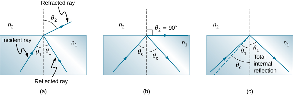
The critical angle \(θ_c\) for a combination of materials is defined to be the incident angle \(θ_1\) that produces an angle of refraction of \(90°\). That is, \(θ_c\) is the incident angle for which \(θ_2=90°\). If the incident angle \(θ_1\) is greater than the critical angle, as shown in Figure \(\PageIndex{1c}\), then all of the light is reflected back into medium 1, a condition called total internal reflection. (As Figure \(\PageIndex{1}\) shows, the reflected rays obey the law of reflection so that the angle of reflection is equal to the angle of incidence in all three cases.)
Snell’s law states the relationship between angles and indices of refraction. It is given by
\[n_1\sin θ_1=n_2 \sin θ_2. \nonumber \]
When the incident angle equals the critical angle (\(θ_1=θ_c\)), the angle of refraction is \(90°\) (\(θ_2=90°\)). Noting that \(\sin 90°=1\), Snell’s law in this case becomes
\[n_1 \, \sin \, θ_1 = n_2. \nonumber \]
The critical angle \(θ_c\) for a given combination of materials is thus
\[ θ_c = \sin^{−1}\left(\frac{n_2}{n_1}\right)\label{critical} \]
for \(n_1>n_2\).
Total internal reflection occurs for any incident angle greater than the critical angle \(θ_c\), and it can only occur when the second medium has an index of refraction less than the first. Note that this equation is written for a light ray that travels in medium 1 and reflects from medium 2, as shown in Figure \(\PageIndex{1}\).
Example \(\PageIndex{1}\): Determining a Critical Angle
What is the critical angle for light traveling in a polystyrene (a type of plastic) pipe surrounded by air? The index of refraction for polystyrene is 1.49.
Strategy
The index of refraction of air can be taken to be 1.00, as before. Thus, the condition that the second medium (air) has an index of refraction less than the first (plastic) is satisfied, and we can use the equation
\[θ_c=\sin^{−1}\left(\frac{n_2}{n_1}\right) \nonumber \]
to find the critical angle \(θ_c\), where \(n_2=1.00\) and \(n_1=1.49\).
Solution
Substituting the identified values gives
\[\begin{align} θ_c &= \sin^{−1}\left(\frac{1.00}{1.49}\right) \nonumber \\[4pt] &= \sin^{−1}(0.671) \nonumber \\[4pt] &= 42.2°. \nonumber \end{align} \nonumber \]
Significance
This result means that any ray of light inside the plastic that strikes the surface at an angle greater than 42.2° is totally reflected. This makes the inside surface of the clear plastic a perfect mirror for such rays, without any need for the silvering used on common mirrors. Different combinations of materials have different critical angles, but any combination with \(n_1>n_2\) can produce total internal reflection. The same calculation as made here shows that the critical angle for a ray going from water to air is 48.6°, whereas that from diamond to air is 24.4°, and that from flint glass to crown glass is 66.3°.
At the surface between air and water, light rays can go from air to water and from water to air. For which ray is there no possibility of total internal reflection?
- Answer
-
air to water, because the condition that the second medium must have a smaller index of refraction is not satisfied

Figure \(\PageIndex{1}\): Due to total internal reflection, an underwater swimmer’s image is reflected back into the water where the camera is located. The circular ripple in the image center is actually on the water surface. Due to the viewing angle, total internal reflection is not occurring at the top edge of this image, and we can see a view of activities on the pool deck. (credit: modification of work by “jayhem”/Flickr)
In the photo above, the image of a swimmer underwater is captured by a camera that is also underwater. The swimmer in the upper half of the photograph, apparently facing upward, is, in fact, a reflected image of the swimmer below. The circular ripple near the photograph’s center is actually on the water surface. The undisturbed water surrounding it makes a good reflecting surface when viewed from below, thanks to total internal reflection. However, at the very top edge of this photograph, rays from below strike the surface with incident angles less than the critical angle, allowing the camera to capture a view of activities on the pool deck above water.