
10.5: Oblique Incidence


- Last updated
- Jun 21, 2021
- Save as PDF

( \newcommand{\kernel}{\mathrm{null}\,}\)
When a plane wave falls upon the plane interface between two media the incident and reflected wave-vectors define the plane of incidence, see Figures (10.4.6) and (10.5.7). The direction of the electric field vector in the incident wave may make an arbitrary angle with the plane of incidence. The general case may be treated as the sum of two special cases: an electric vector perpendicular to the plane of incidence (called s-polarized light from the German word for perpendicular, ”senkrecht”), and an electric vector which lies in the plane of incidence (p-polarized light).
10.5.1 S-polarized Waves.
Consider first S-polarized waves, Figure (10.4.6). The incident wave electric vector can be described by the equation
Ey=E0exp(i[x(ksinθ)+z(kcosθ)−ωt]),
where k = ω/c because this wave is incident on the interface from vacuum. Eventually one is going to have to ensure that the tangential components of the electric and magnetic fields are continuous across the interface, and these boundary conditions must hold at any particular time at all points on the interface. This requirement means that all the waves in this problem, both inside the material and on the vacuum side of the interface, must have the same spatial dependence on the co-ordinates which lie in the interface plane. For the present example, Figure (10.6), the incident wave varies with the in-plane co-ordinate like
exp(ixksinθ)=exp(ixωsinθ/c),
therefore this same factor must appear both in the reflected wave and in the transmitted wave that is generated in the region z>0. Since the reflected wave-vector has the same magnitude as the incident wave-vector, k = ω/c as determined by Maxwell’s equations, and since its x-component of the wavevector must be the same as for the incident wave, it follows that the angle of reflection must be the same as the angle of incidence as is shown in Figure (10.4.6). The electric vector of the reflected wave is given by
Ey=ERexp(i[xksinθ−zkcosθ−ωt]).
(Note the change in the sign of the z-component of k). The magnetic field vector in the incident wave must be perpendicular both to the electric field vector and to the wave-vector:
H(i)x=−H0cosθexp(i[xksinθ+zkcosθ−ωt])H(i)z=H0sinθexp(i[x,ksinθ+zkcosθ−ωt])
where H0 = E0/Z0, and Z0=cμ0=√μ0/ϵ0=377 Ohms. The magnetic field vector in the reflected wave must simultaneously be orthogonal to the reflected wave electric vector and also to the wave-vector:
H(R)x=HRcosθexp(i[xksinθ−zkcosθ−ωt])H(R)z=HRsinθexp(i[xksinθ−zkcosθ−ωt])
where HR = ER/Z0. Eqns.(10.5.4 and 10.5.6) satisfy Maxwell’s equations for the vacuum.
The electric field in the transmitted wave will be polarized along y because the material in the region z≥0 is assumed to be linear and isotropic so that a y-directed incident electric field will generate a y-directed transmitted electric field:
Ey=Aexp(i[xksinθ])exp(i[zkz−ωt]).
The Maxwell equation curl(→H)=−∂→B∂t=iωμ0→H becomes
∂Ey∂z=−iωμ0Hx,∂Ey∂x=iωμ0Hz.
The Maxwell equation curl(→H)=∂→D∂t=−iϵrϵ0ω→E becomes
∂Hx∂z−∂Hz∂x=−iωϵrϵ0Ey.
Combine Equations (10.5.9) and (???) to obtain
∂2Ey∂z2+∂2Ey∂x2=−(ωc)2ϵrEy.
This equation requires that
k2z+k2sin2θ=ϵr(ωc)2,
or, since k = ω/c,
k2z=[ϵr−sin2θ](ωc)2.
The z-component of the transmitted wave-vector must therefore be calculated from
kz=√[ϵr−sin2θ](ωc),
where the imaginary part of kz must be chosen to be positive in order that the wave (???) be damped out as the wave travels along the z -direction. The wave-vector component kz will in general be a complex number corresponding to the fact that the relative dielectric constant, ϵr=ϵR+iϵI, is a complex number: here ϵR and ϵI I are both real numbers. A complex index of refraction can be defined for the case of oblique incidence by setting
kz=(nθ+iκθ)(ωc).
the parameters nθ and κθ are explicit functions of the angle of incidence. The electric field transmitted into the material on the right of z=0 will be given by
Ey=Aexp(i[xksinθ])exp(−κθωz/c)exp(i[nθωzc−ωt]),
and from Equations (10.5.9) the magnetic field components are given by
Hx=−(nθ+iκθ)Z0.⋅Aexp(i[xksinθ])exp(−κθωz/c)exp(i[nθωzc−ωt]),Hz=sinθZ0Aexp(i[xksinθ])exp(−κθωz/c)exp(i[nθωzc−ωt]),
where Z0=cμ0=377 Ohms. The planes of constant amplitude are parallel with the plane interface. The planes of constant phase are tilted at an angle ϕ with respect to the interface plane. The wave-vector in the material, which is perpendicular to the planes of constant phase, has components that are given by
kx=(ωc)sinθ,
and
Real(kz)=nθ(ωc),
therefore the tilt angle ϕ illustrated in Figure (10.4.6) can be calculated from
tanϕ=sinθnθ.
In cases for which the dielectric constant can be taken to be real, i.e. negligible losses, one has
km=√[k2sin2θ+k2z]=√ϵr(ωc).
Then
sinϕ=ksinθ√ϵr(ω/c)=sinθ√ϵr.
This is just Snell’s law:
sinθ=√ϵrsinϕ.
For this case a real index of refraction can be defined for the medium, n=√ϵr, and the phase velocity of the wave in the medium is c/n; the refracted wave propagates in the direction specified by the angle ϕ obtained from Snell’s law. In the more general case of a lossy medium the angle between the surfaces of constant phase and the boundary surface must be calculated from Equation (???).
At z=0 the tangential components of →E and →H must be continuous across the interface and this condition determines the amplitudes of the reflected and transmitted waves. One finds
E0+ER=A,
and
−H0cosθ+HRcosθ=−(nθ+iκθ)Z0A,
or, since H0 = E0/Z0 and HR = ER/Z0
−E0+ER=−(nθ+iκθ)cosθA.
The parameters nθ and κθ are defined by equations (???) and (???). The two equations, (???) and (???), can be solved for the amplitudes ER and A in terms of the incident wave amplitude E0.
AE0=2cosθ[cosθ+(nθ+iκθ)],ERE0=(cosθ−(nθ+iκθ)cosθ+(nθ+iκθ)),
where, it will be recalled,
(nθ+iκθ)=√ϵr−sin2θ,
and the sign must be chosen so that κθ>0.
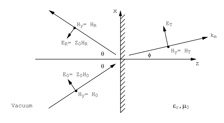
10.5.2 P-polarized Waves.
Arguments for P-polarized light are similar to those for S-polarized light. However, for P-polarized radiation the magnetic field is polarized perpendicular to the plane of incidence, Figure (10.5.7). The incident wave can be written
Hincy=H0exp(i[xksinθ+zkcosθ−ωt]),
Eincx=Z0H0cosθexp(i[xksinθ+zkcosθ−ωt]),
ERz=−Z0HRsinθexp(i[xksinθ−zkcosθ−ωt]),
and for the reflected wave:
HRy=HRexp(i[xksinθ−zkcosθ−ωt]),
ERx=−Z0HRcosθexp(i[xksinθ−zkcosθ−ωt]),
ERz=−Z0HRsinθexp(i[xksinθ−zkcosθ−ωt]).
Inside the material, z≥0, which is assumed to be characterized by a complex relative dielectric constant ϵr, one finds from
curl(→H)=−iωϵrϵ0→E,
∂Hy∂z=iωϵrϵ0Ex,
∂Hy∂x=−iωϵrϵ0Ez,
and from
curl(→E)=−∂→B∂t=iωμ0→H,
∂Ex∂z−∂Ez∂x=iωμ0Hy.
Equations (???) and (???) can be combined to give
∂2Hy∂x2+∂2Hy∂z2=−ϵr(ωc)2Hy.
The solution of Equation (???) can be written
Hy=HTexp(i[xksinθ+zkz−ωt]),
where
k2sin2θ+k2z=ϵr(ωc)2.
In these Equations k=(ω/c). Equation (???) for kz is the same as that which was obtained for the case of an incident S-polarized wave. Solving for kz one obtains:
kz=√[ϵr−sin2θ](ωc),
or
kz=(nθ+iκθ)(ωc),
where
nθ+iκθ=√[ϵr−sin2θ],
and the sign of the square root must be chosen so as to make the imaginary part of kz positive in order to describe an optical disturbance that is attenuated as z increases.
From the form of the magnetic field, Equation (???), and from the Maxwell Equations (???), it follows that
Ex=(nθ+iκθ)ϵrZ0HTexp(ixksinθ)exp(−κθωz/c)exp(i[nθωzc−ωt]),
Ez=−sinθϵrZ0HTexp(ixksinθ)exp(−κθωz/c)exp(i[nθωzc−ωt]).
And from the boundary conditions at z=0 (continuity of the tangential components of →E and →H) one finds:
H0+HR=HT,
Z0H0cosθ−Z0HRcosθ=(nθ+iκθ)ϵrZ0HT,
or
H0−HR=(nθ+iκθ)ϵrcosθHT.
These two equations can be solved to obtain
HTH0=2ϵrcosθ(ϵrcosθ+(nθ+iκθ)),
HRH0=(ϵrcosθ−(nθ+iκθ)ϵrcosθ+(nθ+iκθ)),
where (nθ+iκθ)=√[ϵr−sin2θ] and κθ>0.
Notice that div(→D)=0 for both the S- and P-polarized waves. This is obvious for the S-polarized light because the electric field has only a y-component and this component does not depend upon the y co-ordinate, Equation (???). For P-polarized radiation, from Equations (???),
∂Ex∂x+∂Ez∂z=0,
so that div(→E)=0 and, since →D=ϵrϵ0→E, so also div(→D)=0. There are no free charges set up in the material for either S- or P-polarized radiation. The condition div(→D)=0 can also be deduced directly from the Maxwell’s equation
curl(→H)=∂→D∂t=−iω→D,
because the divergence of any curl is zero. It is easy to show by direct calculation that the normal component of the magnetic field →B is continuous across the surface of the dielectric material for both S- and P-polarized radiation.
10.5.3 Oblique Incidence on a Lossless Material.
For a material in which the losses are very small so that the imaginary part of the dielectric constant can be neglected, a real index of refraction can be defined by
n=√ϵr.
For S-polarized radiation the reflection and transmission coefficients, Equations (10.5.29), become
RS=ERE0=(cosθ−ncosϕcosθ+ncosϕ),
TS=ETE0=(2cosθcosθ+ncosϕ),
where sinϕ=sinθ/n.
For P-polarized radiation, and n=√ϵr a real number, the reflection and transmission coefficients (???) become
RP=HRH0=(ncosθ−cosϕncosθ+cosϕ),
TP=HTH0=(2ncosθncosθ+cosϕ),
where, as above, sin ϕ = sin θ/n and n=√ϵr. The relation
nθ=√n2−sin2θ=ncosϕ
has also been used.