13.4: Double Slit
- Page ID
- 5874
\( \newcommand{\vecs}[1]{\overset { \scriptstyle \rightharpoonup} {\mathbf{#1}} } \)
\( \newcommand{\vecd}[1]{\overset{-\!-\!\rightharpoonup}{\vphantom{a}\smash {#1}}} \)
\( \newcommand{\dsum}{\displaystyle\sum\limits} \)
\( \newcommand{\dint}{\displaystyle\int\limits} \)
\( \newcommand{\dlim}{\displaystyle\lim\limits} \)
\( \newcommand{\id}{\mathrm{id}}\) \( \newcommand{\Span}{\mathrm{span}}\)
( \newcommand{\kernel}{\mathrm{null}\,}\) \( \newcommand{\range}{\mathrm{range}\,}\)
\( \newcommand{\RealPart}{\mathrm{Re}}\) \( \newcommand{\ImaginaryPart}{\mathrm{Im}}\)
\( \newcommand{\Argument}{\mathrm{Arg}}\) \( \newcommand{\norm}[1]{\| #1 \|}\)
\( \newcommand{\inner}[2]{\langle #1, #2 \rangle}\)
\( \newcommand{\Span}{\mathrm{span}}\)
\( \newcommand{\id}{\mathrm{id}}\)
\( \newcommand{\Span}{\mathrm{span}}\)
\( \newcommand{\kernel}{\mathrm{null}\,}\)
\( \newcommand{\range}{\mathrm{range}\,}\)
\( \newcommand{\RealPart}{\mathrm{Re}}\)
\( \newcommand{\ImaginaryPart}{\mathrm{Im}}\)
\( \newcommand{\Argument}{\mathrm{Arg}}\)
\( \newcommand{\norm}[1]{\| #1 \|}\)
\( \newcommand{\inner}[2]{\langle #1, #2 \rangle}\)
\( \newcommand{\Span}{\mathrm{span}}\) \( \newcommand{\AA}{\unicode[.8,0]{x212B}}\)
\( \newcommand{\vectorA}[1]{\vec{#1}} % arrow\)
\( \newcommand{\vectorAt}[1]{\vec{\text{#1}}} % arrow\)
\( \newcommand{\vectorB}[1]{\overset { \scriptstyle \rightharpoonup} {\mathbf{#1}} } \)
\( \newcommand{\vectorC}[1]{\textbf{#1}} \)
\( \newcommand{\vectorD}[1]{\overrightarrow{#1}} \)
\( \newcommand{\vectorDt}[1]{\overrightarrow{\text{#1}}} \)
\( \newcommand{\vectE}[1]{\overset{-\!-\!\rightharpoonup}{\vphantom{a}\smash{\mathbf {#1}}}} \)
\( \newcommand{\vecs}[1]{\overset { \scriptstyle \rightharpoonup} {\mathbf{#1}} } \)
\(\newcommand{\longvect}{\overrightarrow}\)
\( \newcommand{\vecd}[1]{\overset{-\!-\!\rightharpoonup}{\vphantom{a}\smash {#1}}} \)
\(\newcommand{\avec}{\mathbf a}\) \(\newcommand{\bvec}{\mathbf b}\) \(\newcommand{\cvec}{\mathbf c}\) \(\newcommand{\dvec}{\mathbf d}\) \(\newcommand{\dtil}{\widetilde{\mathbf d}}\) \(\newcommand{\evec}{\mathbf e}\) \(\newcommand{\fvec}{\mathbf f}\) \(\newcommand{\nvec}{\mathbf n}\) \(\newcommand{\pvec}{\mathbf p}\) \(\newcommand{\qvec}{\mathbf q}\) \(\newcommand{\svec}{\mathbf s}\) \(\newcommand{\tvec}{\mathbf t}\) \(\newcommand{\uvec}{\mathbf u}\) \(\newcommand{\vvec}{\mathbf v}\) \(\newcommand{\wvec}{\mathbf w}\) \(\newcommand{\xvec}{\mathbf x}\) \(\newcommand{\yvec}{\mathbf y}\) \(\newcommand{\zvec}{\mathbf z}\) \(\newcommand{\rvec}{\mathbf r}\) \(\newcommand{\mvec}{\mathbf m}\) \(\newcommand{\zerovec}{\mathbf 0}\) \(\newcommand{\onevec}{\mathbf 1}\) \(\newcommand{\real}{\mathbb R}\) \(\newcommand{\twovec}[2]{\left[\begin{array}{r}#1 \\ #2 \end{array}\right]}\) \(\newcommand{\ctwovec}[2]{\left[\begin{array}{c}#1 \\ #2 \end{array}\right]}\) \(\newcommand{\threevec}[3]{\left[\begin{array}{r}#1 \\ #2 \\ #3 \end{array}\right]}\) \(\newcommand{\cthreevec}[3]{\left[\begin{array}{c}#1 \\ #2 \\ #3 \end{array}\right]}\) \(\newcommand{\fourvec}[4]{\left[\begin{array}{r}#1 \\ #2 \\ #3 \\ #4 \end{array}\right]}\) \(\newcommand{\cfourvec}[4]{\left[\begin{array}{c}#1 \\ #2 \\ #3 \\ #4 \end{array}\right]}\) \(\newcommand{\fivevec}[5]{\left[\begin{array}{r}#1 \\ #2 \\ #3 \\ #4 \\ #5 \\ \end{array}\right]}\) \(\newcommand{\cfivevec}[5]{\left[\begin{array}{c}#1 \\ #2 \\ #3 \\ #4 \\ #5 \\ \end{array}\right]}\) \(\newcommand{\mattwo}[4]{\left[\begin{array}{rr}#1 \amp #2 \\ #3 \amp #4 \\ \end{array}\right]}\) \(\newcommand{\laspan}[1]{\text{Span}\{#1\}}\) \(\newcommand{\bcal}{\cal B}\) \(\newcommand{\ccal}{\cal C}\) \(\newcommand{\scal}{\cal S}\) \(\newcommand{\wcal}{\cal W}\) \(\newcommand{\ecal}{\cal E}\) \(\newcommand{\coords}[2]{\left\{#1\right\}_{#2}}\) \(\newcommand{\gray}[1]{\color{gray}{#1}}\) \(\newcommand{\lgray}[1]{\color{lightgray}{#1}}\) \(\newcommand{\rank}{\operatorname{rank}}\) \(\newcommand{\row}{\text{Row}}\) \(\newcommand{\col}{\text{Col}}\) \(\renewcommand{\row}{\text{Row}}\) \(\newcommand{\nul}{\text{Nul}}\) \(\newcommand{\var}{\text{Var}}\) \(\newcommand{\corr}{\text{corr}}\) \(\newcommand{\len}[1]{\left|#1\right|}\) \(\newcommand{\bbar}{\overline{\bvec}}\) \(\newcommand{\bhat}{\widehat{\bvec}}\) \(\newcommand{\bperp}{\bvec^\perp}\) \(\newcommand{\xhat}{\widehat{\xvec}}\) \(\newcommand{\vhat}{\widehat{\vvec}}\) \(\newcommand{\uhat}{\widehat{\uvec}}\) \(\newcommand{\what}{\widehat{\wvec}}\) \(\newcommand{\Sighat}{\widehat{\Sigma}}\) \(\newcommand{\lt}{<}\) \(\newcommand{\gt}{>}\) \(\newcommand{\amp}{&}\) \(\definecolor{fillinmathshade}{gray}{0.9}\)The Feynman Double Slit
Here we discuss one of the two major paradoxes that we use to introduce Quantum Mechanics. It is the double slit experiment for bullets, water waves and electrons. Although many people have experimented with the systems to be discussed and written about them, Richard Feynman's treatment is so clear that physicists often call it the "Feynman" double slit. At the end, 2 references are given so you may read the "master" on this topic.
Operational Definitions for "Particles" and "Waves"
An "operational definition" is just a well-defined repeatable experimental procedure whose result defines a word or words. For example, one may have wide-ranging discussions of the meaning of the word intelligence. An operational definition of intelligence which side-steps these discussions could be:
I administer the Stanford-Binet IQ test to a person and score the result. The person's intelligence is the score on the test.
Here we build operational definitions for the words "particles" and "waves."
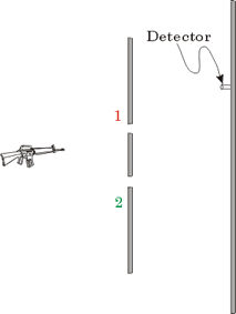
First we discuss "particles" and will take as our prototype bullets from a machine gun. We have the machine gun, a piece of armor-plate in which two small slits have been cut, labeled"1" and "2", a detector and a solid armor-plate backstop. The detector is quite simple: it is a can in which we have placed some sand. We will turn the gunner loose for, say, a 1 minute burst, and then see how many bullets arrive in the can. We empty the can, and then move it to a different position on the backstop, turn the gunner loose for another 1 minute burst, and see how many bullets have arrived at the new position. By repeating the procedure, we can determine the distribution of bullets arriving at different positions on the backstop.
It turns out the the machine gunner is drunk, so that he is spraying the bullets randomly in all directions.
|
The apparatus is shown to the right. We will do three different "experiments" with this apparatus. |
 |
|
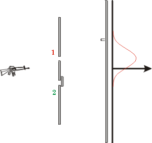
First we close up the lower slit and measure the distribution of bullets arriving at the backstop from the upper slit. For some bullet sizes and slit widths, although many bullets will go straight through the slit a significant fraction will ricochet off the armor plate. So the distribution of bullets looks as shown by the curve to the right. |
 |
| Next we close up the upper slit, and measure the distribution of bullets arriving at the backstop from the lower slit. The shape, shown as the curve to the right, is the same as the previous one, but has been shifted down. | 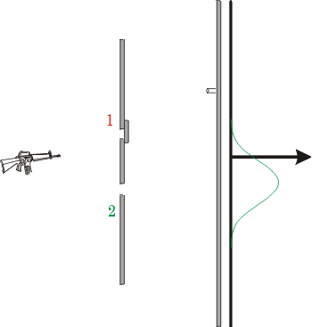 |
| Finally, we leave both slits open and measure the distribution of bullets arriving at the backstop from both slits. The result is the solid curve shown to the right. Also shown as dashed lines are the results we just got for bullets from the upper slit and bullets from the lower slit. | 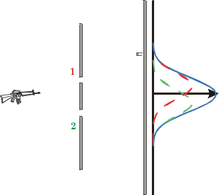 |
The result is just what you probably have predicted: the number of bullets arriving from both slits is just the sum of the bullets from the upper slit and the bullets from the lower slit.
It will be useful later for you to realize that since the path of a single bullet is random, the distributions we were measuring above are essentially measuring the probability that a given bullet will arrive at a particular position at the backstop.
Now we turn our attention to waves. My high school physics teacher had a device called "ripple tank" which is just a tank made of plexiglass which could be filled with water. Various devices would tap the surface of the water, causing water waves to spread out from the device. One may insert slits and other objects in the path of the waves. The whole apparatus was mounted on an overhead projector, so could be used as a class demonstration. My teacher absolutely loved his ripple tank, so physics class was basically water-play. I don't know quite why he was so enamored with the device or what he expected us to learn from it, but to this day when I think of a prototype wave I think of water waves in a ripple tank. So we will repeat the double slit experiments we just did in a ripple tank.
|
First we show the apparatus. The thing that is tapping the surface of the water is the little black circle in the middle of all the concentric circles. The concentric circles are the water waves spreading out away from the source. Just as before we have two slits and a backstop. Just in front of the backstop is our "detector", which is just a cork floating on the surface of the water. Se we measure how much the cork bobs up and down and determine the amount of wave energy arriving at that position at the backstop. Moving the cork to other positions will allow us the determine the distribution of wave energy at the backstop. |
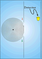 |
|
Now we close up the lower slit, and measure the distribution of wave energy arriving at the backstop just from the upper slit. For some combinations of slit width and wavelength, there will be significant spreading of the wave after it passes through the slit. If you have ever observed surf coming in through a relatively small slit in a seawall, you may have observed this. The distribution is shown by the curve to the right. Note that it is very similar to the distribution of bullets from a single slit. |
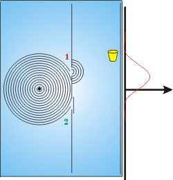 |
|
Now we close the upper slit and measure the distribution of wave energy arriving from the lower slit, as shown to the right. |
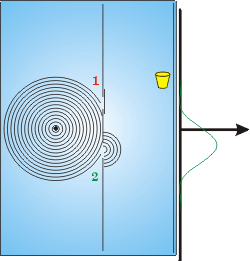 |
|
Finally, we leave both slits open and measure the distribution. The result is shown to the right. As we did for the bullets, the dashed lines show the results we just obtained for the distribution from the upper and lower slits alone, while the solid line is the result for both slits open. This looks nothing like the result for bullets. There are places where the total wave energy is much greater than the sum from the two slits, and other places where the energy is almost zero. Such a distribution is called an interference pattern. |
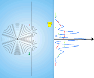 |
This completes the "operational definition" that we need to define waves and particles. In the two slit experiment, a particle does not show an interference pattern and the probability of a particle arriving at a location at the backstop with both slits open is just the sum of the probability of it arriving through the upper slit plus the probability of it arriving through the lower slit. A wave shows an interference pattern.
If you think about conservation of energy, you may worry a bit about the interference pattern for waves. There is no problem. The total energy in the interference pattern is equal to the energy arriving from the upper slit plus the energy arriving from the lower slit: the interference pattern re-arranges the energy but conserves the total amount of energy.
We can explain the interference pattern for waves. When the two waves from the two slits arrive at some position at the backstop, except for right in the middle they will have traveled different distances from the slits. This means that their "waving" may not be in sync.
|
The figure to the right shows two waves totally "out of phase" with each other. Their sum is always zero. This is basically what is happening at the minima in the interference pattern. |
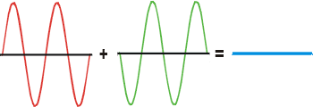 |
|
The figure to the right shows the two waves in phase. The total wave is the sum of the two. This is what is occurring at the maxima in the interference pattern. |
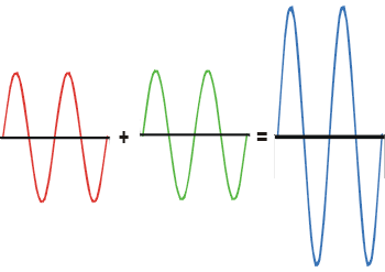 |
The Two Slit Experiment for Light
In ancient Greece there was a controversy about the nature of light. Euclid, Ptolemy and others thought that "light" was some sort of ray that travels from the eye to the observed object. The atomists and Aristotle assumed the reverse. Nearly 800 years after Ptolemy, circa 965 CE, in Basra in what is now Iraq, Abu Ali al-Hasan Ibn al-Haytham (Alhazen) settled the controversy with a clever argument. He said that if you look at the Sun for a long time you will burn your eyes: this is only possible if the light is coming from the Sun to our eyes, not vice versa.
| In 1672 another controversy erupted over the nature of light: Newton argued that light was some sort of a particle, so that light from the sun reaches the earth because these particles could travel through the vacuum. Hooke and Huygens argued that light was some sort of wave. In 1801 Thomas Young put the matter to experimental test by doing a double slit experiment for light. The result was an interference pattern. Thus, Newton was wrong: light is a wave. The figure shows an actual result from the double slit experiment for light. | 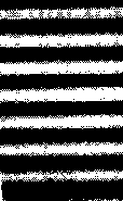 |
Of course, we haven't said anything about what is "waving" or in what medium it is waving. But, in terms of our operational definition it is clear that light is a wave of something.
Electron Guns
An electron gun, such as in a television picture tube, generates a beam of electrons. In this section we discuss how it works. These details are not important for our primary purpose here, so you may jump to the next section by clicking here.
|
A diagram of an electron gun appears to the right. There are two vertical metal plates; the right hand plate has a small hole cut in it. A voltage source, indicated by V, maintains a voltage across the plates, with the left hand plate negative and the right hand plate positive. When a metal plate is heated, a process called thermionic emission literally boils electrons off the surface of the metal. Normally the electrons only make it a fraction of a millimeter away; this is because when the electron boiled off the surface of the metal, it left that part of the plate with a net positive electric charge which pulls the electron right back into the plate. |
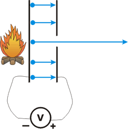 |
In the figure, we are heating up the left hand plate so thermionic electrons will be boiled off the surface. But because of the voltage difference being maintained across the plate, electrons that boil off between the two plates do not fall back into the plate, but instead are attracted to the right hand positive plate. Most of the electrons crash into the positive plate, as shown. However, the electron in the middle would have crashed into the plate except that we have cut a hole in that part of it. So we get a beam of electrons out of this "electron gun."
In real electron guns, such as at the back of a TV picture tube, the negative plate is not heated with a campfire as in our figure. Instead, a small filament of wire has a current passed through it. The filament heats up, glows red, and heats up the negative plate. You may have seen that red glow in the back of a TV picture tube.
We control the speed of the electrons in the beam with the voltage, and the number of electrons by how hot we make the negatively charged plate.
One more small point. Because the hole in the right hand plate is not of zero size, electrons can emerge in directions slightly away from perfectly horizontal. Thus, the beam of electrons will tend to "spray" somewhat.
| From now on we will put the electron gun in a black box, and represent the electron beam coming from it as shown to the right. |  |
The Two Slit Experiment for Electrons
|
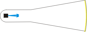
In the previous section we discussed how to produce a beam of electrons from an electron gun. Here we place the electron gun inside a glass tube that has had all the air evacuated. The right hand glass screen has its inside coated with a phosphor that will produce a small burst of light when an electron strikes it. In a TV picture tube, for example, fields direct the beam of electrons to the desired location, the intensities of the electrons are varied depending on where we are steering the beam, and our minds and/or eyes interpret the flashes as the image we are seeing on the television. |
 |
| Property | Value |
|---|---|
| Mass | 9.11 × 10⁻³¹kg |
| Electric Charge | 1.60 × 10⁻¹⁹Coulombs |
| Spin angular momentum | 5.28 × 10⁻³⁵Joule-seconds |
Now, "everybody knows" that electrons are particles. They have a well defined mass, electric charge, etc. Some of those properties are listed to the right. Waves do not have well defined masses etc.
When an electron leaves the electron gun, a fraction of a second later a flash of light appears on the screen indicating where it landed. A wave behaves differently: when a wave leaves the source, it spreads out distributing its energy in a pattern as discussed at the beginning of this document.
|
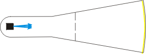
Except, when we place two slits in the path of the electrons, as shown, on the screen we see an interference pattern! In fact, what we see on the screen looks identical to the double slit interference pattern for light that we saw earlier. |
 |
If this seems very mysterious, you are not alone. Understanding what is going on here is in some sense equivalent to understanding Quantum Mechanics. I do not understand Quantum Mechanics. Feynman admitted that he never understood Quantum Mechanics. It may be true that nobody can understand Quantum Mechanics in the usual meaning of the word "understand."
We will now extend our understanding of our lack of understanding. One possibility about the origins of the interference pattern is that the electrons going through the upper slit are somehow interacting with the electrons going through the lower slit. Note that we have no idea what such a mechanism could be, but are a little desperate to understand what is going on here. We can explore this idea by slowing down the rate of electrons from the gun so that only one electron at a time is in the system. What we do is fire an electron, see where the flash of light occurs on the phosphor screen, wait a while for everything to settle down, then fire another electron, noting where it lands on the screen.
After we have fired a large number of electrons, we will discover that the distribution of electrons is still the interference pattern.
I have prepared a small Flash animation that simulates this result. You may access the animation by clicking on the red![]() button to the right. The file size is 6.4k. You may get the Flash player free from http://www.macromedia.com/; our animation is for Version 5 or later of the player.
button to the right. The file size is 6.4k. You may get the Flash player free from http://www.macromedia.com/; our animation is for Version 5 or later of the player.
You may wish to know that in the animation, the position of the electron is generated randomly using a Monte Carlo technique. Thus, if you "Rewind" the animation to start it over, the build-up of the histogram is almost certain to not be identical to the previous "trial."
We conclude that whatever is going on to cause the interference pattern does not involve two or more electrons interacting with each other. And yet, with one electron at a time in the system, with both slits open there are places on the screen where the electrons do not go, although with only one slit open some electrons do end up at that position.
Now, to get an interference pattern we take a wave, split it up into two parts, send each part through one of the slits, and then recombine the waves. Does this mean that a single electron is somehow going through both slits at once? This too is amenable to experimental test.
| The result of doing the test turns out to be independent of the details of how the experiment is done, so we shall imagine a very simple arrangement: we place a light bulb behind the slits and look to see what is going on. Note that in a real experiment, the light bulb would have to be smaller than in the figure and tucked in more tightly behind the slits so that the electrons don't collide with it. | 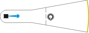 |
We will see a small flash of light when an electron passes through the slits.
What we see is that every electron is acting completely "normal": one-half the electrons are going through the upper slit, one-half are going through the lower slit, and which is going to be the case for a given electron appears to be random. A small (24k) gif animation of what we might see in this experiment may be seen here.
|
But meanwhile, we have a colleague watching the flashes of light on the phosphor coated screen who says "Hey, the interference pattern has just gone away!" And in fact the distribution of electrons on the screen is now exactly the same as the distribution of machine gun bullets that we saw above. The figure to the right is what our colleague sees on the screen. |
 |
Evidently, when we look at what is going on at the slits we cause a qualitative and irreversible change in the behavior of the electrons. This is usually called the "Heisenberg Uncertainty Principle."
Everyone has always known that doing any measurement on any system causes a disturbance in the system. The classical paradigm has been that at least in principle the disturbance can be minimised to the point that it is negligible.
Is it possible to minimise the disturbance being caused by the light bulb? We can turn down the intensity of the light it is emitting. However, if we try it, just at the point that the light is getting so faint that we are missing some of the electrons, the interference pattern starts to come back! In fact, if the light intensity is, say, such that we are missing one-half of the electrons, we have one-half an interference pattern and one-half a particle distribution. So this attempt to minimise the disturbance didn't work out: we still don't know what is going on at the slits when we see the interference pattern.
There is yet another way to minimise the disturbance. The light contains energy, and it turns out that if we increase the wavelength of the light, towards the infrared, the energy of each part of the light goes down. Perhaps if we decrease the energy in the light we won't be scattering it off the electrons so violently. So, we start increasing the wavelength of the light emitted by the light bulb. We continue to see all the electrons, and at first we always see that one-half of them are going through the upper slit and one-half are going through the lower slit.
However, our ability to resolve two positions in space by looking depends on the wavelength of the light that we are seeing with. And just at the point that the wavelength of the light from the lightbulb gets so large that although we can see the electrons we can't tell which slit they went through, the interference pattern comes back.
A student once remarked that we should do a "better" experiment. The Heisenberg Uncertainty Principle says that such a better experiment does not exist. Einstein in particular devoted a lot of time trying to devise such a better measurement; all his attempts failed.
The conclusion of all this is that there is no experiment that can tell us what the electrons are doing at the slits that does not also destroy the interference pattern. This seems to imply that there is no answer to the question of what is going on at the slits when we see the interference pattern. The path of the electron from the electron gun to the screen is not knowable when we see the interference pattern. As Heisenberg said, "The path [of the electron] comes into existence only when we observe it."
We will be discussing interpretations of what all this may mean in great detail later. For now I will briefly mention a "standard" if incomplete interpretation. If we think that the probability of where the electron is in space is a wave, then when we don't look the probability wave has two pieces at the slits, representing the fact that there is a 50% chance the electron went through the upper slit and a 50% chance it went through the lower slit. These two probability waves from the two slits, then, recombine at the screen and cause the interference pattern.
When we look, we "collapse the state" in a 100% chance it went through one slit and a 0% chance it went through the other. And in this circumstance the two probability waves for the two slits cannot then recombine at the screen to cause an interference pattern: for each electron there is only one non-zero probability wave.
Finally, then, we have two contradictory yet complementary models of the two-slit experiment for electrons. In one model the electron is a particle that somehow exhibits an interference pattern. In the other model, the electron is a wave that somehow manifests as a particle whenever we look at it.
![]() A Flash animation of these two models, both incomplete, may be accessed by clicking the red button to the right. The file size is 23k and will appear in a separate window.
A Flash animation of these two models, both incomplete, may be accessed by clicking the red button to the right. The file size is 23k and will appear in a separate window.
References
- Richard Feynman, The Character of Physical Law (MIT, 1965), Chapter 6
- Richard P. Feynman, Robert B. Leighton and Matthew Sands, The Feynman Lectures on Physics (Addison-Wesley, 1963), Vol III, Chapter 1
Author
David M. Harrison, Dept. of Physics, Univ. of Toronto, mailto:harrison@physics.utoronto.ca.

