
21.4: The Torque on a Current-Carrying Loop


- Last updated
- Mar 28, 2024
- Save as PDF
( \newcommand{\kernel}{\mathrm{null}\,}\)
- Section 11.3 on torque.
- Section 16.4 on electric dipoles.
As noted in Example 21.3.1, the net magnetic force on any closed loop immersed in a uniform magnetic field is zero. Consider, for example, the current-carrying rectangular loop of height, h, and width, w, immersed in a uniform magnetic field, →B, as illustrated in Figure 21.4.1 (note that the field is not perpendicular to the plane of the loop, as it was in Example 21.3.1).
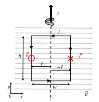
The magnetic force on the two horizontal sections of the wire are zero, since the current is co-linear with the magnetic field along those sections. In the left vertical section (with current flowing downwards), the magnetic force is out of the page (positive z direction), and is given by:
→F=IhBˆz
Similarly, the force on the right vertical section (with current flowing upwards) will have the same magnitude but the opposite direction. The net force on the loop is thus zero.
However, the net torque on the loop about its vertical axis of symmetry (shown by the vertical dashed line in the figure) is not zero. The total torque is found by summing the torques from the forces exerted on the two vertical sections of wire:
→τ=→r×→F+(−→r×−→F)=2→r×F=2(−w2ˆx)×IhBˆz=IBwh(−ˆx׈z)∴→τ=IBwh(ˆy)
where →r is the vector from the axis of rotation to the location where the force is exerted.
Magnetic Dipole Moment
Describing the torque on a loop can be difficult in three dimensions, so we introduce the “magnetic dipole moment” to simplify the description.
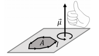
If a closed loop carries a current, I, the magnetic dipole moment vector, →μ, is defined such that it has a magnitude:
μ=IA
where, A, is the area enclosed by the loop. The direction of the magnetic dipole moment vector is such that it is perpendicular to the surface defined by the loop. Of the two such possible directions, the direction of the magnetic dipole moment is given by the right-hand rule for axial vectors; by curling the fingers in the direction of the current, the thumb will point in the direction of the magnetic dipole moment. This is illustrated in Figure 21.4.2.
In terms of the magnetic dipole moment, the torque on a loop, with magnetic dipole moment, →μ, immersed in a magnetic field, →B, is given by:
→τ=→μ×→B
The magnitude of the torque is given by:
τ=μBsinθ
where θ is the angle between the magnetic dipole moment and the magnetic field vectors.
We can verify that this formula gives the correct torque for the rectangular loop in Figure 21.4.1 that we calculated above. The magnetic dipole moment of that loop is given by:
→μ=IAˆz=Iwhˆz
where the direction of the vector is given by the right hand rule for axial vectors (out of the page, since the current is in the counter-clockwise direction in Figure 21.4.1). The torque on the loop is thus:
→τ=→μ×→B=(Iwhˆz)×(Bˆx)=IBwh(ˆy)
as we found previously.
The magnetic dipole moment can be used to describe a current-carrying loop in a magnetic field. That is, instead of drawing a loop carrying current, we can equivalently simply draw the associated magnetic dipole moment vector. This is useful because the magnetic dipole moment vector behaves in the same way as a bar magnet (with the tip of the arrow acting like a North pole). Indeed, a magnetic field will always create a torque that will try to align the magnetic dipole moment with the magnetic field, just as the needle of a compass experience a torque if it is not aligned with the magnetic field of the Earth. The torque from the magnetic field is then zero when the magnetic dipole moment is parallel to the magnetic field (as the cross-product between co-linear vectors is zero).
Figure 21.4.3 shows a way to visualize a current-carrying loop in a magnetic field using its magnetic dipole moment vector, →mu.
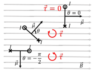
Three loops are shown (as lines), seen from above, and the direction of the current in each loop is shown as going in or out of the page. Equivalently, one can simply draw the magnetic dipole moment vector for each loop (perpendicular to the plane of the loop). For the top loop, the magnetic dipole moment is parallel to the magnetic field, so the magnetic field exerts no torque. For the middle loop, the magnetic dipole moment makes an angle θ with the magnetic field vector, so that the torque on that loop has a magnitude given by τ=μBsinθ, and points into the page (clockwise rotation). The bottom loop makes an angle of −π/2 with the magnetic field, which results in a torque in the counter-clockwise direction. In all cases, the torque is such that it always tries to align the magnetic dipole moment vector with the magnetic field, just as if the magnetic dipole moment were the needle of a compass.
Determine the magnetic dipole moment of the electron orbiting a hydrogen atom, if you assume that the electron is in a circular orbit with a radius of R=0.5\unicode{xC5}.
Solution
As the electron orbits around the circle, it results in a circular loop of current, I. The current is the rate at which charge passes through a point per unit time. If the electron orbit has a period, T, then the corresponding current, I, is given by:
\begin{aligned} I=\frac{\Delta Q}{\Delta t} = \frac{e}{T}\end{aligned}
The centripetal force on the electron is provided by the Coulomb force, F_C, exerted by the proton, which allows us to obtain the orbital speed, and thus the period of the orbit:
\begin{aligned} F_C &= m\frac{v^2}{R}\\[4pt] k\frac{e^2}{R^2}&= m\frac{v^2}{R}\\[4pt] \therefore v &=\sqrt{\frac{ke^2}{mR}}\\[4pt] \therefore T &= \frac{2\pi R}{v}\end{aligned}
The magnetic dipole moment is then given by:
\begin{aligned} \mu &=IA = \frac{e}{T}\pi R^{2}=\frac{ev}{2\pi R}\pi R^{2}\frac{1}{2}evR=\frac{1}{2}\sqrt{\frac{ke^{4}R}{m}} \\[4pt] &=\frac{1}{2}\sqrt{\frac{(9\times 10^{9}\text{N/C}^{2}\cdot\text{m}^{2})(1.6\times 10^{-19}\text{C})^{4}(0.5\unicode{xC5})}{(9.1\times 10^{-31}\text{kg})}}=9\times 10^{24}\text{A}\cdot\text{m}^{2} \end{aligned}
Discussion
In this example we calculated the orbital magnetic dipole moment of the electron in a hydrogen atom. This was a very simple model, since in reality, electrons do not orbit atoms in circular orbits, and one must use quantum mechanics to describe the motion precisely.
Potential energy for a magnetic moment in a magnetic field
A magnetic dipole moment in a magnetic field behaves in the same way as an electric dipole in an electric field. By analogy, we can then define a potential energy, U, for a magnetic dipole moment, \vec \mu in a magnetic field, \vec B:
U=-\vec\mu\cdot\vec B=-\mu B\cos\theta
where \theta is the angle between the magnetic moment and the magnetic field. If a magnetic dipole is not aligned with a magnetic field and it is released, it will start to rotate (gain rotational kinetic energy) until it reaches a minimum in potential energy (\theta = 0). The magnetic moment would oscillate back and forth about \theta =0 if there are no losses. Note that the point where \theta = \pi, is an unstable equilibrium.
When a magnetic dipole moment is paralell with a magnetic field and points in the same direction as the magnetic field, it will have...
- ... its maximum torque and maximum potential energy.
- ... its maximum torque and minimum potential energy.
- ... its minimum torque and maximum potential energy.
- ... its minimum torque and minimum potential energy.
- Answer
When a magnetic dipole moment is placed such that the torque from the magnetic field is maximized, it will have...
- ... zero potential energy.
- ... its minimum potential energy.
- Answer