
12.2: Rolling motion


- Last updated
- May 17, 2024
- Save as PDF
( \newcommand{\kernel}{\mathrm{null}\,}\)
In this section, we examine how to model the motion of an object that is rolling along a surface, such as the motion of a bicycle wheel. Consider the motion of a wheel of radius, R, rotating with angular velocity, →ω, about an axis perpendicular to the wheel and through its center of mass, as observed in the center of mass frame. This is illustrated in Figure 12.2.1.
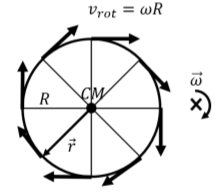
In the frame of reference of the center of mass, each point on the edge of the wheel has a velocity, →vrot, due to rotation given by:
→vrot=→ω×→r
where →r is a vector (of magnitude R) from the center of mass to the corresponding point on the edge of the wheel (shown in Figure 12.2.1 for a point on the lower left of the wheel). The vector →r is always perpendicular to →ω, so that the speed of all points on the edge, as measured in the frame of reference of the center of mass, is the same:
vrot=ωR
as illustrated in Figure 12.2.1.
Now, suppose that the whole wheel is moving, as it rolls on the ground, such that the center of mass of the wheel moves with a velocity, →vCM, as illustrated in Figure 12.2.2.
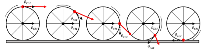
In the frame of reference of the ground, each point on the edge of the wheel will have a velocity →v given by:
→v=→vrot+→vCM
That is, in the frame reference of the ground, each point will have a velocity obtained by (vectorially) adding its velocity relative to the center of mass, →vrot, and the velocity of the center of mass relative to the ground, →vCM. This is illustrated in Figure 12.2.2 for one specific point, shown in red. The red vector corresponds to the velocity of the red point as the wheel rotates, and is obtained by adding the velocity of the center of mass, →vCM, and the velocity, →vrot, relative to the center of mass (shown as the dashed vector, tangent to the edge of the wheel).
Consider, specifically, the instant in time when the red point is at the bottom of the wheel, where the wheel makes contact with the ground. If the wheel is not slipping with respect to the ground, then the point is, at that instant, at rest relative to the ground. We call this type of motion “rolling without slipping”; the point on the rotating object that is in contact with the ground is instantaneously at rest relative to the ground. This is the scenario illustrated in Figure 12.2.2.
For the point in contact with the ground, the vectors →vrot and →vCM are anti-parallel, horizontal, and must sum to zero. Writing out the horizontal component of the velocity of that point (choosing the positive direction to be in the direction of the velocity of the center of mass):
v=−vrot+vCM=0∴vrot=vCM
and we find that, for rolling without slipping, the speed due to rotation about the center of mass has to be equal to the speed of the center of mass. The speed due to rotation about the center of mass can be expressed using the angular velocity of the wheel about the center of mass (Equation 12.2.1). For rolling without slipping, we thus have the following relationship between angular velocity and the speed of the center of mass:
ωR=vCM(rolling without slipping)
It makes sense for the angular velocity to be related to the speed of the center of mass. The faster the wheel rotates, the faster the center of mass will move. If the wheel is slipping with respect to the ground, then the point of contact is no longer stationary relative to the ground, and there is no relation between the angular velocity and the speed of the center of mass. For rolling with slipping, imagine the motion of your bicycle wheel as you try to ride your bike on a slick sheet of ice.
For rolling without slipping, the magnitude of the linear acceleration of the center of mass, aCM, is similarly related to the magnitude of the angular acceleration of the wheel, α, about the center of mass:
aCM=dvCMdt=ddtωR=Rdωdt∴aCM=Rα
For rolling without slipping (Figure 12.2.2), the speed of the point on the wheel that is in contact with the ground is 0. What is the speed of the point at the top of the wheel?
- 0.
- vCM.
- 2vCM.
- None of the above.
- Answer
- C.
Solution
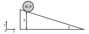
A disk of mass M and radius R is placed on an incline at a height h above the ground. The incline makes an angle θ with respect to the horizontal, as shown in Figure 12.2.3. If the disk starts at rest and rolls without slipping down the incline, what speed will the center of mass have when the disk reaches the bottom of the incline? We can use the conservation of mechanical energy to determine the speed of the center of mass at the bottom of the incline, as there are no non-conservative forces doing work on the disk. If we choose to define gravitational potential energy such that it is zero at the bottom of the incline, we can write the total mechanical energy of the disk at the top of the incline as:
E=K+U=(0)+Mgh
where the kinetic energy is zero, since the disk starts at rest1. At the bottom of the incline, the disk will have only kinetic energy, since the potential energy at the bottom is defined to be zero. The kinetic energy of the disk will have a component from the rotation of the disk about the center of mass, with angular speed ω, and a component from the translation of the center of mass with speed vCM. The mechanical energy at the bottom of the incline is thus:
E′=K′+U=K′rot+K′trans+(0)=12ICMω2+12Mv2cm
Since the disk is rolling without slipping, its angular speed is related to the speed of center of mass:
ω=vCMR
The moment of inertia of the disk about its center of mass is given by:
ICM=12MR2
We can thus write the mechanical energy at the bottom of the incline as:
E′=12ICMω2+12Mv2cm=12(12MR2)(vCMR)2+12Mv2cm=34Mv2cm
Applying conservation of energy allows us to determine the speed of the center of mass at the bottom of the incline:
E=E′Mgh=34Mv2cm∴vCM=√43gh
Discussion
This example showed how we can use the conservation of energy to model the motion of an object that is rolling without slipping. The constraint of rolling without slipping allowed for the angular speed of the object to be related to the speed of its center of mass.
A hoop, a disk, and a sphere roll without slipping down an incline. If they are all released at the same time, in what order will they arrive at the bottom?
- Hoop, disk, sphere.
- Sphere, disk, hoop.
- Disk, sphere, hoop.
- Disk, hoop, sphere.
- Answer
- B.
The instantaneous axis of rotation
When an object is rolling without slipping, we can model its motion as the superposition of rotation about the center of mass and translational motion of the center of mass, as in the previous section. However, because the point of contact between the rolling object and the ground is stationary, we can also model the motion as if the object were instantaneously rotating with angular velocity, →ω, about a stationary axis through the point of contact. That is, we can model the motion as rotation only, with no translation, if we choose an axis of rotation through the point of contact between the ground and the wheel.
We call the axis through the point of contact the “instantaneous axis of rotation”, since, instantaneously, it appears as if the whole wheel is rotating about that point. This is illustrated in Figure 12.2.4, which shows, in red, the velocity vector for each point on the edge of the wheel, relative to the instantaneous axis of rotation. Because the axis of rotation is fixed to the ground, the velocity of each point about that axis of rotation corresponds to the same velocity relative to the ground that is depicted in Figure 12.2.2.
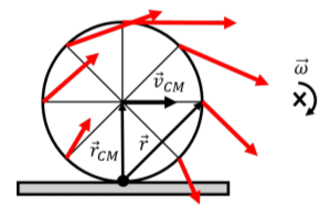
In particular, the angular velocity, →ω, about the instantaneous axis of rotation is the same as when we model the motion as translation plus rotation about the center of mass ,as in the previous section. Indeed, relative to the instantaneous axis of rotation, the center of mass must still have a velocity →vCM, which is given by:
→vCM=→ω×→rCM∴vCM=ωR
where →rCM is the vector from the axis of rotation to the center of mass. This is the same condition for rolling without slipping that we found before. Similarly, the velocity of any point on the wheel, relative to the ground, is given by:
→v=→ω×→r
where →r is the vector from the axis of rotation to the point of interest (shown in Figure 12.2.4 for the point on the right side of the wheel). In particular, the velocity vector (in red) for any point is always perpendicular to the vector →r for that point, which was not necessarily obvious when modeling the motion as rotation plus translation, as in Figure 12.2.2.
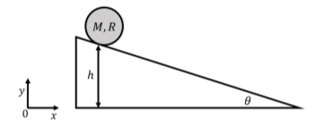
A disk of mass M and radius R is placed on an incline at a height h above the ground. The incline makes an angle θ with respect to the horizontal, as shown in Figure 12.2.5. What is the angular acceleration of the disk, about an axis through its center of mass, as it rolls without slipping down the slope?
Solution
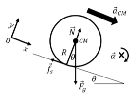
In order to determine the angular acceleration of the disk about the center of mass, we need to model the forces that are exerted on the disk. The forces exerted on the disk are:
- →Fg, the weight of the disk, exerted downwards at the center of mass, with magnitude Mg.
- →N, a normal force perpendicular to the incline, exerted by the incline at the point of contact with the disk.
- →fs, a force of static friction parallel to the incline, exerted by the incline at the point of contact with the disk. Without this force, the disk would simply slide down the incline without rotating.
These forces are illustrated in Figure 12.2.6, along with the acceleration of the center of mass, and our choice of coordinate system (we choose the x axis parallel to the acceleration of the center of mass, to facilitate applying Newton’s Second Law).
The angular acceleration of the disk about the center of mass, →α is given by Newton’s Second Law for rotational dynamics:
→τext=ICM→α
where →τext is the net external torque on the disk about the center of mass (which will be in the negative z direction).
The only force that can exert a torque about the center of mass is the force of static friction. Gravity has a lever arm of zero and the normal force is anti-parallel to the vector that goes from the center of mass to the point where the force is exerted. The net torque about the center of mass is thus:
→τext=→τfs=→rfs×→fs=−Rfsˆz
The angular acceleration will thus be in the negative z direction, and the magnitude is given by:
α=τextICM=Rfs12MR2=2fsMR
However, we do not know the magnitude of the force of static friction. We can use the x and y components of Newton’s Second Law to determine it (with acceleration of the center of mass in the x direction):
∑Fx=Fgsinθ−fs=MaCM∑Fy=N−Fgcosθ=0
Because the disk is rolling without slipping, the acceleration of the center of mass is related to the angular acceleration of the disk:
acm=αR
The x component of Newton’s Second Law can thus be used to determine the magnitude of the force of static friction in terms of the angular acceleration:
Mgsinθ−fs=MαR∴fs=Mgsinθ−MαR
We can then substitute out the force of friction from our previous formula for the angular acceleration:
α=2fsMR=2Mgsinθ−2MαRMR=2gsinθR−2α∴α=2gsinθ3R
Instead of modeling the motion of the disk as rotation about the center of mass and translation of the center of mass, we can also model it about the instantaneous axis of rotation.
The angular acceleration about the instantaneous axis of rotation will be the same as the angular acceleration about the center of mass. About the instantaneous axis of rotation, only the force of gravity can exert a torque, since the normal force and the force of friction both have a lever arm of zero. The torque from the force of gravity, about the instantaneous axis of rotation is:
→τg=−FgRsinθˆz=−MgRsinθˆz
The torque from the force of gravity is equal to the moment of inertia of the disk about the instantaneous axis of rotation, I, multiplied by its angular acceleration:
τext=τg=Iα∴α=τgI=MgRsinθI
The moment of inertia about the instantaneous axis of rotation is easily found using the parallel axis theorem:
I=ICM+MR2=12MR2+MR2=32MR2
This allows us to find the angular acceleration of the disk:
α=MgRsinθI=MgRsinθ32MR2=2gsinθ3R
as we found previously, but in this case, we did not need to use Newton’s Second Law to determine the force of friction.
Discussion
We saw that we can model the dynamics of the rolling body using either an axis through the center of mass, or an axis through the instantaneous axis of rotation. The latter was easier in this case, because it did not require using Newton’s Second Law.
By using an axis through the center of mass to model the motion of the disk, it was clear that the force of static friction is required in order for the disk to rotate. Without the force of static friction, the disk would slide along the surface of the incline. The disk could still rotate if there is a force of kinetic friction that causes a torque that rotates the disk. If the surface were completely frictionless, the disk would simply slide down the incline, and we could model it as a sliding block. If the incline is too steep the force of static friction is no longer sufficient to provide the necessary torque required for the angular acceleration to be that which corresponds to rolling without slipping, and the disk would slip.
Footnotes
1. Technically, the potential energy should be taken for the height of the center of mass, which is a distance hCM=h+Rcosθ from the ground at the top of the incline, and a height h′CM=R at the bottom of the incline. The net difference in height for the center of mass is thus hCM−h′CM=h+R(1−cosθ). If we assume that h is much bigger than R, then this is negligible, otherwise, that is what we should use instead of h for the potential energy.