
1.5: Amateur Radio Equipment Basics


- Last updated
- Oct 5, 2024
- Save as PDF
( \newcommand{\kernel}{\mathrm{null}\,}\)
By the end of this section, you will be able to:
- Define transceiver, and its basic operation in an radio system.
- Define repeater, and explain why repeaters are used.
We will begin our discussion of radio equipment with a basic overview of the topic. The AM or FM broadcast radios that are common in everyday life are receivers only. In other words, they only receive the electromagnetic waves that are broadcast from the remote AM or FM radio station and then convert the received signal to sound. While this setup is reasonable for music or news, it lacks the interactivity that most Amateur Radio operators desire to make two-way contacts.
Transceivers
In contrast, radios that are able to both receive and transmit are called transceivers. The basic components of a transceiver are illustrated in Fig. 1.5.1. The operator communicating by voice can switch between receiving and transmitting, usually through a "push-to-talk" (PTT) button on a microphone. This button enables a transmit/receive switch so that the transmitter sends its electrical signals through a feed line out to the antenna. The antenna then converts the electrical signals in the radio to the electromagnetic waves that travel outwards into the air. When the button is released, the transmit-receive switch connects the antenna to the receiver, and any electromagnetic waves detected by the antenna are then converted into an electrical signal that can be turned into audio. The transceiver operates using simplex (also half-duplex) communication as it can simply receive or transmit using the same frequency but not both simultaneously.


Figure 1.5.2 shows photos of actual transceivers useable for Amateur Radio. In both models, a "push-to-talk" button enables the operator to speak into the microphone and transmit the signal. When the button is released, the radios will return to receiving the signals from the connected antenna.


Figure 1.5.2: (left to right) Examples of an Amateur Radio base-station transceiver [2] and handheld transceiver [3]. For the base-station transceiver, the feed line connects to the back of the unit and is not shown. For the handheld transceiver, the feed line is just the connector from the antenna to the unit.
Repeaters
In the VHF and UHF range (above 30 MHz), the signals from the radio's antenna travel will usually travel primarily along their line of sight [4], which is as far as the wave can travel in a straight line away from the antenna and still directly interact with another antenna, as illustrated in Figure 1.5.3.

Figure 1.5.3: Illustration of the idealized range of "line of sight" propagation of electromagnetic waves. (Note that the antenna size is exaggerated to show the effect.) [5]
To extend the ability of a station to communicate beyond its "line of sight" range, repeaters are employed. As the name suggests, repeaters are special radios which have antennas that receive signals transmitted on a channel of a particular frequency, and then re-transmit (repeat) the incoming signal on a different channel of a second frequency that is offset slightly from the receiving frequency. Figure 1.5.4 shows a block diagram of the operation of a repeater.

Figure 1.5.4: Block diagram of a repeater. Signals received by the antenna on a channel of one frequency are re-transmited on a second channel of a different frequency. [6]
A second station that is not within the range of the first station can then communicate with the first station using the repeater as an intermediary, as illustrated in Figure 1.5.5(B). In some cases, the communication may even be further extended using a network of multiple repeaters. As suggested by Fig. 1.5.5., it is advantageous to place repeaters in high locations like towers, tall building, hills, or mountains to maximize their range.
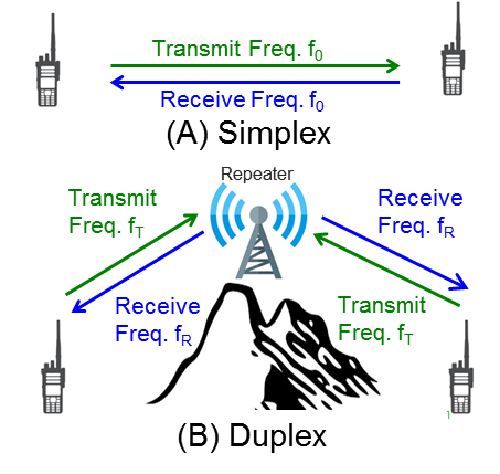
Figure 1.5.5: (A) Simplex communication occurs on the same frequency between the stations with each station either transmitting or receiving but not both at the same time. (B) Duplex communication uses a repeater as intermediate station with transmitting and receiving on different frequencies, possibly at the same time. [7]
Other examples of communication systems which use duplexing include wired and cellular telephones, although the method for the duplexing may be different than described above [8].
References
- Kumon RE. Block diagram of a transceiver. (CC BY-SA 4.0)
- Wikimedia Commons contributors. File:Yaesu FT991.jpg [Internet]. Wikimedia Commons. (Image: CC0 1.0; mick m43, All mode HF-6m-2m-70cm-AM-SSB-FM-C4FM Fusion Yaesu FT-991 transceiver, Annotation: CC BY-SA 4.0, Ronald E. Kumon)
- Wikimedia Commons contributors. File:Baofeng UV-5R transceiver 5.jpg [Internet]. Wikimedia Commons. (Image: CC BY-SA 4.0; Barbara Kaminskaya, Dual band amateur VHF/UHF transceiver Baofeng UV-5R, Annotation: CC BY-SA 4.0, Ronald E. Kumon)
- Wikipedia contributors. Line-of-sight propagation [Internet]. Wikipedia, The Free Encyclopedia.
- Wikimedia Commons contributors. File:VHF propagation.png [Internet]. Wikimedia Commons. (CC BY-SA 4.0; Rudolf Davis Strazds, VHF radio wave propagation)
- Kumon RE. Block diagram of a repeater. (CC BY-SA 4.0)
- Wikimedia Commons contributors. File:Repeater Talk around channel.png [Internet]. Wikimedia Commons. (Original image: CC0 1.0; Goodtiming8871, Repeater Talk around channel diagram, Modifications: CC BY-SA 4.0; Ronald Kumon)
- Wikipedia contributors. Duplex (telecommunications) [Internet]. Wikipedia, The Free Encyclopedia.
Technician Exam Questions
Relevant exam questions include: T7A02, T1F09.