
10.2: Reflection
- Page ID
- 66129

\( \newcommand{\vecs}[1]{\overset { \scriptstyle \rightharpoonup} {\mathbf{#1}} } \)
\( \newcommand{\vecd}[1]{\overset{-\!-\!\rightharpoonup}{\vphantom{a}\smash {#1}}} \)
\( \newcommand{\dsum}{\displaystyle\sum\limits} \)
\( \newcommand{\dint}{\displaystyle\int\limits} \)
\( \newcommand{\dlim}{\displaystyle\lim\limits} \)
\( \newcommand{\id}{\mathrm{id}}\) \( \newcommand{\Span}{\mathrm{span}}\)
( \newcommand{\kernel}{\mathrm{null}\,}\) \( \newcommand{\range}{\mathrm{range}\,}\)
\( \newcommand{\RealPart}{\mathrm{Re}}\) \( \newcommand{\ImaginaryPart}{\mathrm{Im}}\)
\( \newcommand{\Argument}{\mathrm{Arg}}\) \( \newcommand{\norm}[1]{\| #1 \|}\)
\( \newcommand{\inner}[2]{\langle #1, #2 \rangle}\)
\( \newcommand{\Span}{\mathrm{span}}\)
\( \newcommand{\id}{\mathrm{id}}\)
\( \newcommand{\Span}{\mathrm{span}}\)
\( \newcommand{\kernel}{\mathrm{null}\,}\)
\( \newcommand{\range}{\mathrm{range}\,}\)
\( \newcommand{\RealPart}{\mathrm{Re}}\)
\( \newcommand{\ImaginaryPart}{\mathrm{Im}}\)
\( \newcommand{\Argument}{\mathrm{Arg}}\)
\( \newcommand{\norm}[1]{\| #1 \|}\)
\( \newcommand{\inner}[2]{\langle #1, #2 \rangle}\)
\( \newcommand{\Span}{\mathrm{span}}\) \( \newcommand{\AA}{\unicode[.8,0]{x212B}}\)
\( \newcommand{\vectorA}[1]{\vec{#1}} % arrow\)
\( \newcommand{\vectorAt}[1]{\vec{\text{#1}}} % arrow\)
\( \newcommand{\vectorB}[1]{\overset { \scriptstyle \rightharpoonup} {\mathbf{#1}} } \)
\( \newcommand{\vectorC}[1]{\textbf{#1}} \)
\( \newcommand{\vectorD}[1]{\overrightarrow{#1}} \)
\( \newcommand{\vectorDt}[1]{\overrightarrow{\text{#1}}} \)
\( \newcommand{\vectE}[1]{\overset{-\!-\!\rightharpoonup}{\vphantom{a}\smash{\mathbf {#1}}}} \)
\( \newcommand{\vecs}[1]{\overset { \scriptstyle \rightharpoonup} {\mathbf{#1}} } \)
\(\newcommand{\longvect}{\overrightarrow}\)
\( \newcommand{\vecd}[1]{\overset{-\!-\!\rightharpoonup}{\vphantom{a}\smash {#1}}} \)
\(\newcommand{\avec}{\mathbf a}\) \(\newcommand{\bvec}{\mathbf b}\) \(\newcommand{\cvec}{\mathbf c}\) \(\newcommand{\dvec}{\mathbf d}\) \(\newcommand{\dtil}{\widetilde{\mathbf d}}\) \(\newcommand{\evec}{\mathbf e}\) \(\newcommand{\fvec}{\mathbf f}\) \(\newcommand{\nvec}{\mathbf n}\) \(\newcommand{\pvec}{\mathbf p}\) \(\newcommand{\qvec}{\mathbf q}\) \(\newcommand{\svec}{\mathbf s}\) \(\newcommand{\tvec}{\mathbf t}\) \(\newcommand{\uvec}{\mathbf u}\) \(\newcommand{\vvec}{\mathbf v}\) \(\newcommand{\wvec}{\mathbf w}\) \(\newcommand{\xvec}{\mathbf x}\) \(\newcommand{\yvec}{\mathbf y}\) \(\newcommand{\zvec}{\mathbf z}\) \(\newcommand{\rvec}{\mathbf r}\) \(\newcommand{\mvec}{\mathbf m}\) \(\newcommand{\zerovec}{\mathbf 0}\) \(\newcommand{\onevec}{\mathbf 1}\) \(\newcommand{\real}{\mathbb R}\) \(\newcommand{\twovec}[2]{\left[\begin{array}{r}#1 \\ #2 \end{array}\right]}\) \(\newcommand{\ctwovec}[2]{\left[\begin{array}{c}#1 \\ #2 \end{array}\right]}\) \(\newcommand{\threevec}[3]{\left[\begin{array}{r}#1 \\ #2 \\ #3 \end{array}\right]}\) \(\newcommand{\cthreevec}[3]{\left[\begin{array}{c}#1 \\ #2 \\ #3 \end{array}\right]}\) \(\newcommand{\fourvec}[4]{\left[\begin{array}{r}#1 \\ #2 \\ #3 \\ #4 \end{array}\right]}\) \(\newcommand{\cfourvec}[4]{\left[\begin{array}{c}#1 \\ #2 \\ #3 \\ #4 \end{array}\right]}\) \(\newcommand{\fivevec}[5]{\left[\begin{array}{r}#1 \\ #2 \\ #3 \\ #4 \\ #5 \\ \end{array}\right]}\) \(\newcommand{\cfivevec}[5]{\left[\begin{array}{c}#1 \\ #2 \\ #3 \\ #4 \\ #5 \\ \end{array}\right]}\) \(\newcommand{\mattwo}[4]{\left[\begin{array}{rr}#1 \amp #2 \\ #3 \amp #4 \\ \end{array}\right]}\) \(\newcommand{\laspan}[1]{\text{Span}\{#1\}}\) \(\newcommand{\bcal}{\cal B}\) \(\newcommand{\ccal}{\cal C}\) \(\newcommand{\scal}{\cal S}\) \(\newcommand{\wcal}{\cal W}\) \(\newcommand{\ecal}{\cal E}\) \(\newcommand{\coords}[2]{\left\{#1\right\}_{#2}}\) \(\newcommand{\gray}[1]{\color{gray}{#1}}\) \(\newcommand{\lgray}[1]{\color{lightgray}{#1}}\) \(\newcommand{\rank}{\operatorname{rank}}\) \(\newcommand{\row}{\text{Row}}\) \(\newcommand{\col}{\text{Col}}\) \(\renewcommand{\row}{\text{Row}}\) \(\newcommand{\nul}{\text{Nul}}\) \(\newcommand{\var}{\text{Var}}\) \(\newcommand{\corr}{\text{corr}}\) \(\newcommand{\len}[1]{\left|#1\right|}\) \(\newcommand{\bbar}{\overline{\bvec}}\) \(\newcommand{\bhat}{\widehat{\bvec}}\) \(\newcommand{\bperp}{\bvec^\perp}\) \(\newcommand{\xhat}{\widehat{\xvec}}\) \(\newcommand{\vhat}{\widehat{\vvec}}\) \(\newcommand{\uhat}{\widehat{\uvec}}\) \(\newcommand{\what}{\widehat{\wvec}}\) \(\newcommand{\Sighat}{\widehat{\Sigma}}\) \(\newcommand{\lt}{<}\) \(\newcommand{\gt}{>}\) \(\newcommand{\amp}{&}\) \(\definecolor{fillinmathshade}{gray}{0.9}\)Reflection
When a wave reaches the interface between two different media, typically some of the wave will bounce back into the original medium. This process is known as reflection. A familiar example of reflection is optical reflection in mirrors, where light waves reflect off a smooth surface. Another familiar example of reflection comes from water waves, as the waves travel they reflect off objects that are floating in the water, and also reflect off the walls of the container holding the water. Most of us are familiar with the concept of echoes, which are the reflections of sound waves. Any kind of wave can undergo reflection.
Our goal is to figure out the direction of the waves upon reflection. If we are observing reflected light knowing the direction of the reflected rays will enable us to extrapolate to the image formed by those reflected rays. In the next section, we will apply these ideas to analyzing images formed by different types of mirrors.
Consider a point source of light that sends out a spherical wave toward an imaginary flat plane, as in the left diagram below. When the wave reaches this plane, then according to Huygens's principle, we can look at every point on the plane and treat it as a point source for an individual wavelet (center diagram below). These wavelets are not in phase, because they are all travel different distances from the source to the plane, and when they are superposed, we know the result is what we see, which is a continued spherical wave (right diagram below).
Figure 10.2.1: Spherical Wave Passes Through an Imaginary Plane

Now suppose the plane is not imaginary, but instead reflects the wave. Every point on this plane becomes a source of a wavelet, but this time, the wave created by these wavelets is going in the opposite direction. The wavelets have the same relative phases as in the previous case, and they are completely symmetric, so they superpose to give the same total wave as before, with the exception that it is a mirror image of the case of the imaginary plane.
Figure 10.2.2: Spherical Wave Reflecting off a Reflecting Plane
Thanks to the symmetry of the situation, it's not difficult to see that the reflected wave is identical to a spherical wave that has originated from a point on the opposite side of the reflecting plane, exactly the same distance from the plane as the source, and along the line that runs through the source perpendicular to the surface.
Figure 10.2.3: Image of Reflected Wave

Of course, there isn't actually a point light source on the other side of the reflecting plane, it's just that someone looking at the reflected light – no matter where they look from – will see the wave originating from the direction of that point. We call such a point an image of the original source of the light.
Now let's put this result in terms of light rays. To do this, we need a source and an observer, and this case, we will require also that a reflection has taken place. Once again drawing the rays perpendicular to the wave fronts, we get the following image.
Figure 10.2.4: Reflection in Terms of Rays

It's clear from the symmetry of the situation that the angle the ray makes with the perpendicular (the horizontal dotted line) to the reflecting plane as it approaches, is the same as the angle it makes after it is reflected. From now on we will stick with rays when describing reflection, without the complication of spherical waves and Huygen's principle which governs how the waves reflect when they encourage a surface.
The Law of Reflection
The above result gives us the law of reflection. This law is summarized in the image below.
Figure 10.2.5: Law of Reflection
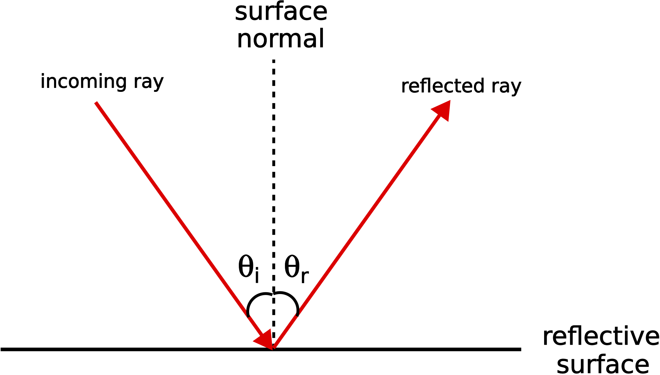
In optics, we will measure the relevant angles in terms of the angle from the surface normal, a line which is perpendicular to the surface from which the ray reflects. The law of reflection states that the incoming angle is defined as the angle of incidence, \(\theta_i\), is equals the reflected angle, the angle of reflection, \(\theta_r\):
\[\theta_i = \theta_r\]
Law of reflection can also be obtained by Fermat's principle that states:
“Light travels between two points along the path that requires the least time, as compared to other nearby paths.”
This rather simple idea will lead us to the same law of reflection demonstrated by Huygen's Principle above. For those who are interested to see the derivation of the law of reflection from Fermat's principle you can read the "digression" below.
Digression: Law of Reflection from Fermat's Principle
Fermat's principle states that light travels between two points such that it takes the shortest amount of time. Consider the diagram below.
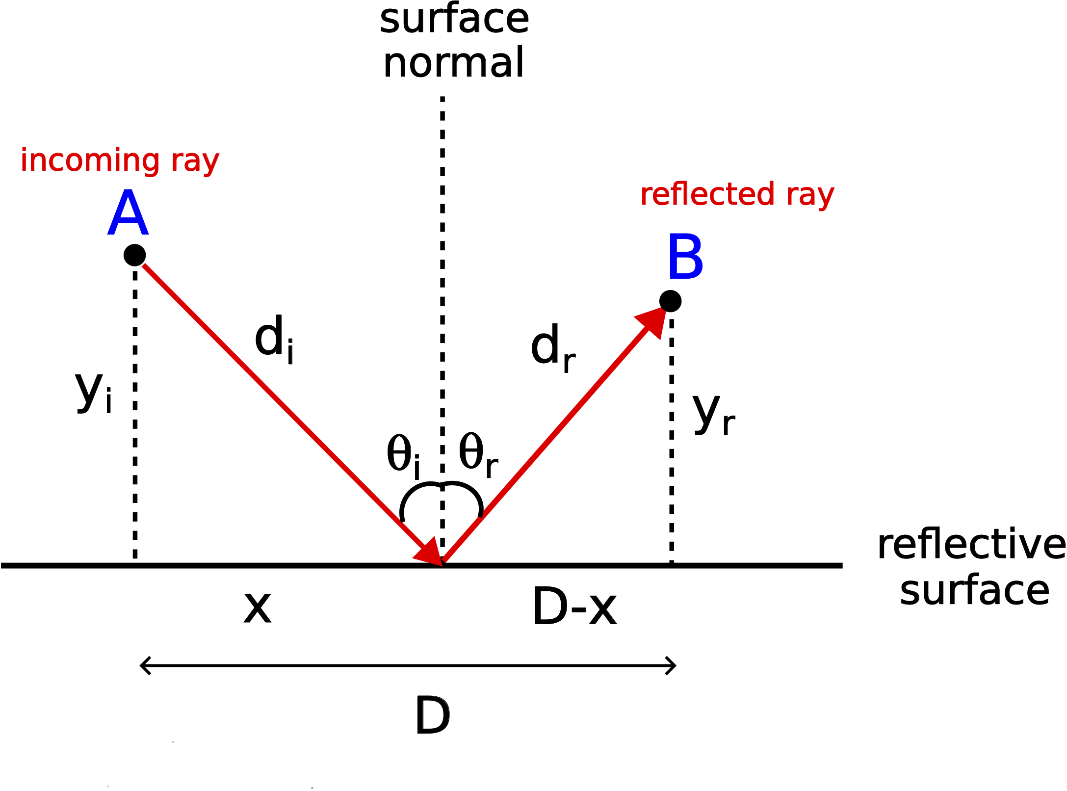
If light was to travel from point A directly to point B, the shortest path would clearly been the straight line connecting the two points. Now let's consider a ray originating from point A that must first reflect from the surface before reaching point B. Our goal is to find the the distance that the ray travels, \(d_i+d_r\), such that the time is minimized. Another way to pose this question is to solve for the distance \(x\), marked in the figure, which insures the shortest path between A and B with a reflection.
The time it takes for the ray to travel from point A to point B is the total distance total distance, \(d_{\text{tot}}=d_i+d_r\), divided by the speed of light, \(c\):
\[t=\dfrac{d_{\text{tot}}}{c}=\dfrac{d_i+d_r}{c}\nonumber\]
Using Pythagorean theorem for each right triangle formed in the figure, the above equation can be written in terms of the horizontal distance \(x\):
\[t=\dfrac{\sqrt{x^2+y_i^2}}{c}+\dfrac{\sqrt{(D-x)^2+y_r^2}}{c}\nonumber\]
The vertical distances \(y_i\) and \(y_r\) and the horizontal distance \(D\) are are fixed for given points A and B. To find the distance \(x\) which minimizes time, we need to differentiate time with the respect to \(x\) and set it to zero:
\[\dfrac{dt}{dx}=0=\dfrac{x}{c\sqrt{x^2+y_i^2}}-\dfrac{D-x}{c\sqrt{(D-x)^2+y_r^2}}\nonumber\]
Expressing the above equation in terms of the angles \(\theta_i\) and \(\theta_r\) we get:
\[\dfrac{dt}{dx}=0=\dfrac{1}{c}(\sin\theta_i-\sin\theta_r)\nonumber\]
Rearranging, we arrive at the law of reflection:
\[\sin\theta_i=\sin\theta_r\Longrightarrow \theta_i=\theta_r\nonumber\]