
10.3: Mirrors
- Page ID
- 66130

\( \newcommand{\vecs}[1]{\overset { \scriptstyle \rightharpoonup} {\mathbf{#1}} } \)
\( \newcommand{\vecd}[1]{\overset{-\!-\!\rightharpoonup}{\vphantom{a}\smash {#1}}} \)
\( \newcommand{\dsum}{\displaystyle\sum\limits} \)
\( \newcommand{\dint}{\displaystyle\int\limits} \)
\( \newcommand{\dlim}{\displaystyle\lim\limits} \)
\( \newcommand{\id}{\mathrm{id}}\) \( \newcommand{\Span}{\mathrm{span}}\)
( \newcommand{\kernel}{\mathrm{null}\,}\) \( \newcommand{\range}{\mathrm{range}\,}\)
\( \newcommand{\RealPart}{\mathrm{Re}}\) \( \newcommand{\ImaginaryPart}{\mathrm{Im}}\)
\( \newcommand{\Argument}{\mathrm{Arg}}\) \( \newcommand{\norm}[1]{\| #1 \|}\)
\( \newcommand{\inner}[2]{\langle #1, #2 \rangle}\)
\( \newcommand{\Span}{\mathrm{span}}\)
\( \newcommand{\id}{\mathrm{id}}\)
\( \newcommand{\Span}{\mathrm{span}}\)
\( \newcommand{\kernel}{\mathrm{null}\,}\)
\( \newcommand{\range}{\mathrm{range}\,}\)
\( \newcommand{\RealPart}{\mathrm{Re}}\)
\( \newcommand{\ImaginaryPart}{\mathrm{Im}}\)
\( \newcommand{\Argument}{\mathrm{Arg}}\)
\( \newcommand{\norm}[1]{\| #1 \|}\)
\( \newcommand{\inner}[2]{\langle #1, #2 \rangle}\)
\( \newcommand{\Span}{\mathrm{span}}\) \( \newcommand{\AA}{\unicode[.8,0]{x212B}}\)
\( \newcommand{\vectorA}[1]{\vec{#1}} % arrow\)
\( \newcommand{\vectorAt}[1]{\vec{\text{#1}}} % arrow\)
\( \newcommand{\vectorB}[1]{\overset { \scriptstyle \rightharpoonup} {\mathbf{#1}} } \)
\( \newcommand{\vectorC}[1]{\textbf{#1}} \)
\( \newcommand{\vectorD}[1]{\overrightarrow{#1}} \)
\( \newcommand{\vectorDt}[1]{\overrightarrow{\text{#1}}} \)
\( \newcommand{\vectE}[1]{\overset{-\!-\!\rightharpoonup}{\vphantom{a}\smash{\mathbf {#1}}}} \)
\( \newcommand{\vecs}[1]{\overset { \scriptstyle \rightharpoonup} {\mathbf{#1}} } \)
\(\newcommand{\longvect}{\overrightarrow}\)
\( \newcommand{\vecd}[1]{\overset{-\!-\!\rightharpoonup}{\vphantom{a}\smash {#1}}} \)
\(\newcommand{\avec}{\mathbf a}\) \(\newcommand{\bvec}{\mathbf b}\) \(\newcommand{\cvec}{\mathbf c}\) \(\newcommand{\dvec}{\mathbf d}\) \(\newcommand{\dtil}{\widetilde{\mathbf d}}\) \(\newcommand{\evec}{\mathbf e}\) \(\newcommand{\fvec}{\mathbf f}\) \(\newcommand{\nvec}{\mathbf n}\) \(\newcommand{\pvec}{\mathbf p}\) \(\newcommand{\qvec}{\mathbf q}\) \(\newcommand{\svec}{\mathbf s}\) \(\newcommand{\tvec}{\mathbf t}\) \(\newcommand{\uvec}{\mathbf u}\) \(\newcommand{\vvec}{\mathbf v}\) \(\newcommand{\wvec}{\mathbf w}\) \(\newcommand{\xvec}{\mathbf x}\) \(\newcommand{\yvec}{\mathbf y}\) \(\newcommand{\zvec}{\mathbf z}\) \(\newcommand{\rvec}{\mathbf r}\) \(\newcommand{\mvec}{\mathbf m}\) \(\newcommand{\zerovec}{\mathbf 0}\) \(\newcommand{\onevec}{\mathbf 1}\) \(\newcommand{\real}{\mathbb R}\) \(\newcommand{\twovec}[2]{\left[\begin{array}{r}#1 \\ #2 \end{array}\right]}\) \(\newcommand{\ctwovec}[2]{\left[\begin{array}{c}#1 \\ #2 \end{array}\right]}\) \(\newcommand{\threevec}[3]{\left[\begin{array}{r}#1 \\ #2 \\ #3 \end{array}\right]}\) \(\newcommand{\cthreevec}[3]{\left[\begin{array}{c}#1 \\ #2 \\ #3 \end{array}\right]}\) \(\newcommand{\fourvec}[4]{\left[\begin{array}{r}#1 \\ #2 \\ #3 \\ #4 \end{array}\right]}\) \(\newcommand{\cfourvec}[4]{\left[\begin{array}{c}#1 \\ #2 \\ #3 \\ #4 \end{array}\right]}\) \(\newcommand{\fivevec}[5]{\left[\begin{array}{r}#1 \\ #2 \\ #3 \\ #4 \\ #5 \\ \end{array}\right]}\) \(\newcommand{\cfivevec}[5]{\left[\begin{array}{c}#1 \\ #2 \\ #3 \\ #4 \\ #5 \\ \end{array}\right]}\) \(\newcommand{\mattwo}[4]{\left[\begin{array}{rr}#1 \amp #2 \\ #3 \amp #4 \\ \end{array}\right]}\) \(\newcommand{\laspan}[1]{\text{Span}\{#1\}}\) \(\newcommand{\bcal}{\cal B}\) \(\newcommand{\ccal}{\cal C}\) \(\newcommand{\scal}{\cal S}\) \(\newcommand{\wcal}{\cal W}\) \(\newcommand{\ecal}{\cal E}\) \(\newcommand{\coords}[2]{\left\{#1\right\}_{#2}}\) \(\newcommand{\gray}[1]{\color{gray}{#1}}\) \(\newcommand{\lgray}[1]{\color{lightgray}{#1}}\) \(\newcommand{\rank}{\operatorname{rank}}\) \(\newcommand{\row}{\text{Row}}\) \(\newcommand{\col}{\text{Col}}\) \(\renewcommand{\row}{\text{Row}}\) \(\newcommand{\nul}{\text{Nul}}\) \(\newcommand{\var}{\text{Var}}\) \(\newcommand{\corr}{\text{corr}}\) \(\newcommand{\len}[1]{\left|#1\right|}\) \(\newcommand{\bbar}{\overline{\bvec}}\) \(\newcommand{\bhat}{\widehat{\bvec}}\) \(\newcommand{\bperp}{\bvec^\perp}\) \(\newcommand{\xhat}{\widehat{\xvec}}\) \(\newcommand{\vhat}{\widehat{\vvec}}\) \(\newcommand{\uhat}{\widehat{\uvec}}\) \(\newcommand{\what}{\widehat{\wvec}}\) \(\newcommand{\Sighat}{\widehat{\Sigma}}\) \(\newcommand{\lt}{<}\) \(\newcommand{\gt}{>}\) \(\newcommand{\amp}{&}\) \(\definecolor{fillinmathshade}{gray}{0.9}\)Plane Mirror
In the previous section we described the law of reflection, and now we will see that this simple law will help us understand how reflective surfaces create images. We will focus on mirrors as the standard reflective surface, although there are many other surfaces such as a clear lake which can produce a sharp reflective images. Let us start with the most standard mirror which we use in our daily lives. This mirror is known as the plane mirror, simply due to its flat shape.
Below is an example of an optical setup for a plane mirror depicted as a vertical line with the reflective surface on the left side. A physical object is placed in front of the reflective surface of the plane mirror. The horizontal dashed line that is perpendicular to the mirror is known as the optical axis, a reference from which we measure the heights of the objects and images formed.
Figure 10.3.1: Image Formation by Plane Mirror
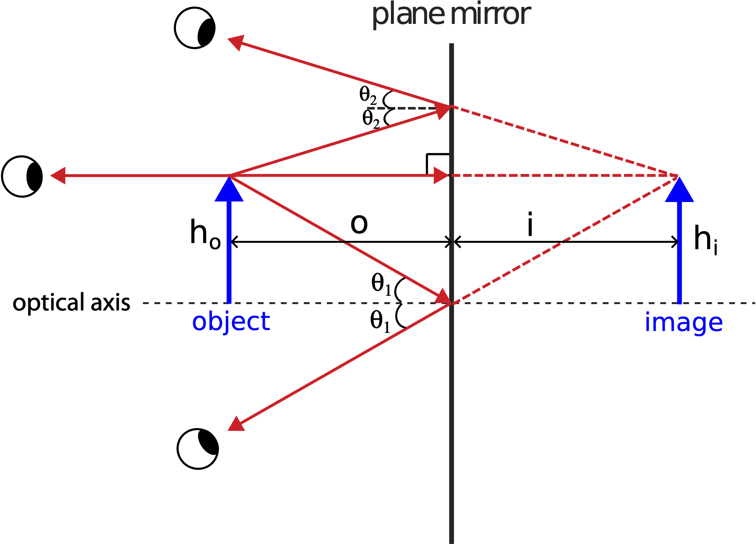
The "object" could be any physical object or a source of light, but we often depict it as an upright arrow. The arrowhead will allow us to distinguish between upright and upside down orientations since, as we will see shortly, some images will have inverted orientations. The object emanates rays in all direction. Some of those rays hit the reflective surface of the mirror and reflect back. An observer standing in front of the mirror will then detect the reflected rays and interpret them as originating from some location from which the rays take a straight path. In other words, the observer detecting the reflected rays does not have any information about the ray initially reflecting before reaching the eyes of the observer.
For convenience, we often choose a few rays originating from the tip of the arrow to analyze. The distinction between the bottom and the top of the arrow is relevant since it will allow us to determine the orientation of the image. In addition, it enables us to find the location of the image of the tip of the object, from which we can extrapolate the image of the remaining object.
In Figure 10.3.1 above we choose three rays and apply the law of reflection to find the path of the reflected rays. The ray which is parallel to the optical axis will meet the mirror perpendicular to its surface (or parallel to the surface normal), which means that it will reflect right back along the same line. To other two rays are shown with the incident angle equal to the reflected angle relative to the surface normal.
In order to determine where the three reflected rays appear to be coming from to the observer, we trace the rays back to determine if they intersect. The location where all three rays meet will be the position of the image of the arrow's tip, since all three rays originated from the tip. As we see from the figure the reflected rays do not cross anywhere in front of the mirror. However, if you continue tracing the rays behind the mirror, you find a specific location where all of them cross. If you drew more rays originating from the tip of the object and applied the law of reflection at the surface of the mirror, you would find that those rays when traced back would also meet at the same location behind the mirror. Since all the rays originating from the object appear to be coming from the location behind the mirror, we observe the image of the object behind the mirror. An image is the appearance of the object at a location different from the physical object.
The reason why the lines behind the mirror are drawn with dashes is that the they are no longer physical rays, but simply the extrapolation of the rays to the location behind the mirror. There is no light penetrating the mirror, yet every time we look in a mirror we see ourself as if appearing from behind the mirror. This type of image is known as virtual, since it is not real light rays that form the image, but rather the tracing of real rays to the location of the image. This definition of a virtual image will become more relevant later, when we compare virtual images to real ones.
The ray that is perpendicular to the mirror and reflects along the same line establishes the fact that the height of the object, \(h_o\), is equal to the height of the image, \(h_i\). This means that the image is neither magnified (enlarged) or de-magnified (reduced), but remains the same size as the object. (Below we will encounter other types of mirrors which can indeed create magnified or de-magnified images). The distance from the mirror to the object is known as the object distance, o. The distance from the mirror to the location of the image is known as the image distance, i. The two right triangles in Figure 10.3.1, one from the optical axis at the mirror to the tip of the object and the other to the tip of the image are identical. From this we can conclude that the object distance is equal to the image distance.
Spherical Mirrors
Although plane mirrors are the most common mirrors we encounter daily, the images they produce are simple to interpret. Much more interesting optical phenomena emerges when we look at mirrors with non-planar shapes. One such group of mirrors is known as spherical mirrors, due to their shape being is a section of a sphere.
Concave Mirrors
Below is a diagram of one such spherical mirror, a concave mirror, named after its shape. A good way to remember the shape of a concave mirror is to think about a "cave". Since a concave mirror is a section of a sphere, it has a well defined center of curvature, C. The distance from the center to the mirror is the radius of curvature, R. We draw the optical axis of the spherical mirror to go right through the center. One special feature of a concave mirror is what happens to incoming plane waves upon reflection. Consider rays that are coming parallel to the optical axis, such as rays originating from a distance object or from a laser. If we apply the law of reflection to all parallel incoming rays, we discover that they all converge (meet) at one point along the optical axis. This point of convergence is called the focal point of the mirror. This result is approximately true if we assume that the incoming rays that are close to the optical axis, due to a small angle approximation. In other words, the simplified model of spherical mirrors that we develop in this chapter applies for objects whose size is much smaller than the radius of curvature of the mirror, or when objects are much closer to the mirror than its radius. We will only consider optical effect using this approximation as it applies to mirrors and lenses (covered in a later section).
Figure 10.3.2: Concave Mirror

The distance from the focal point to the mirror is called the focal length, f. We will not go into the details of the proof, but it can be shown using the small angle approximation that the focal length is equal to half the radius of curvature:
\[f=\dfrac{R}{2}\]
Our next goal is to determine what kind of images concave mirrors produce of objects placed near the mirror. For the plane mirror, we choose a few rays, used the law of reflection to find the path of the reflected rays, and found where those reflected rays converge in order to find the image. We use a similar procedure for spherical mirrors, except we make use of "convenient" incoming rays which will allow us to immediately determine the direction of the reflected rays, without needing to calculate the angle of incidence and reflection. One such ray that travels from the object parallel to the optical axis will reflect through the focal point, by definition of the focal point. By symmetry of the law of reflection, a ray that goes through the focal point will reflect parallel to the optical axis. Another "special ray" is one that goes directly through the center of the sphere. Using a property that line that originates from the center will be perpendicular to the surface of the sphere, we find that, based on the law of reflection, this ray will reflect straight back along the same line since the angle with the normal is zero.
The three "special" rays described above, known as the principle rays, for a concave mirror:
- Principle ray #1: incoming ray parallel to the optical axis will reflect through the focal point.
- Principle ray #2: incoming ray that goes through the focal point will reflect parallel to the optical axis.
- Principle ray #3: incoming rays that goes through the center of curvature will reflect straight back.
These principle rays are depicted with an animation below.
Figure 10.3.3: Principal Rays of a Concave Spherical Mirror
Using rays to determine the location, orientation, and the size of the image is known as ray tracing. We can see that the image where three principal rays in the animation intersect is in front of the mirror, closer to the mirror than the object, and below the optical axis. Unlike for a plane mirror in Figure 10.3.1 where the rays had to be traced behind the mirror to find their intersection and thus image location, in this scenario the actual physical rays intersect in front of the mirror, which make this a real image, compared to a virtual mirror that a plane mirror created. What make real images distinct from virtual ones, is that real images can be projected on a screen. You can place a screen at the location of the image, allowing those rays to be reflected in all directions, so the image can be seen now seen from multiple angles. You cannot project a virtual image on a screen by placing it behind the mirror, since there are no physical rays present there that can reflect from the screen.
If you were to use the same principle rays coming from the middle of the arrow, you would find that they meet at the same location from the mirror as the rays coming from the tip, but halfway closer to the optical axis. Therefore, since the tip is further from the optical axis compared to the rest of the arrow, the image of the object is inverted, appears to be upside down compared to the vertical orientation of the object. The image also appears to be smaller than the object as can be seen in Figure 10.3.3. To determine how much smaller the image compared to the object, you can simply use a ruler and measure the heights of the object and image from the ray tracing in the figure. Likewise, you can measure the distance from the mirror to the image and compare it to the object distance. However, we would like to develop more accurate mathematical relationship between object and image distances and heights. This can be done with pure geometrical arguments.
Alert
Although we will focus on the three principle rays coming from the tip of an object, when determining image sizes and positions, it is important to remember that there are an infinite number of rays that are coming from all position of the the object, many of which will hit the mirror and reflect. All of these rays will then converge at the position of the image for a real image or appear to originate from the location of the image for a virtual image.
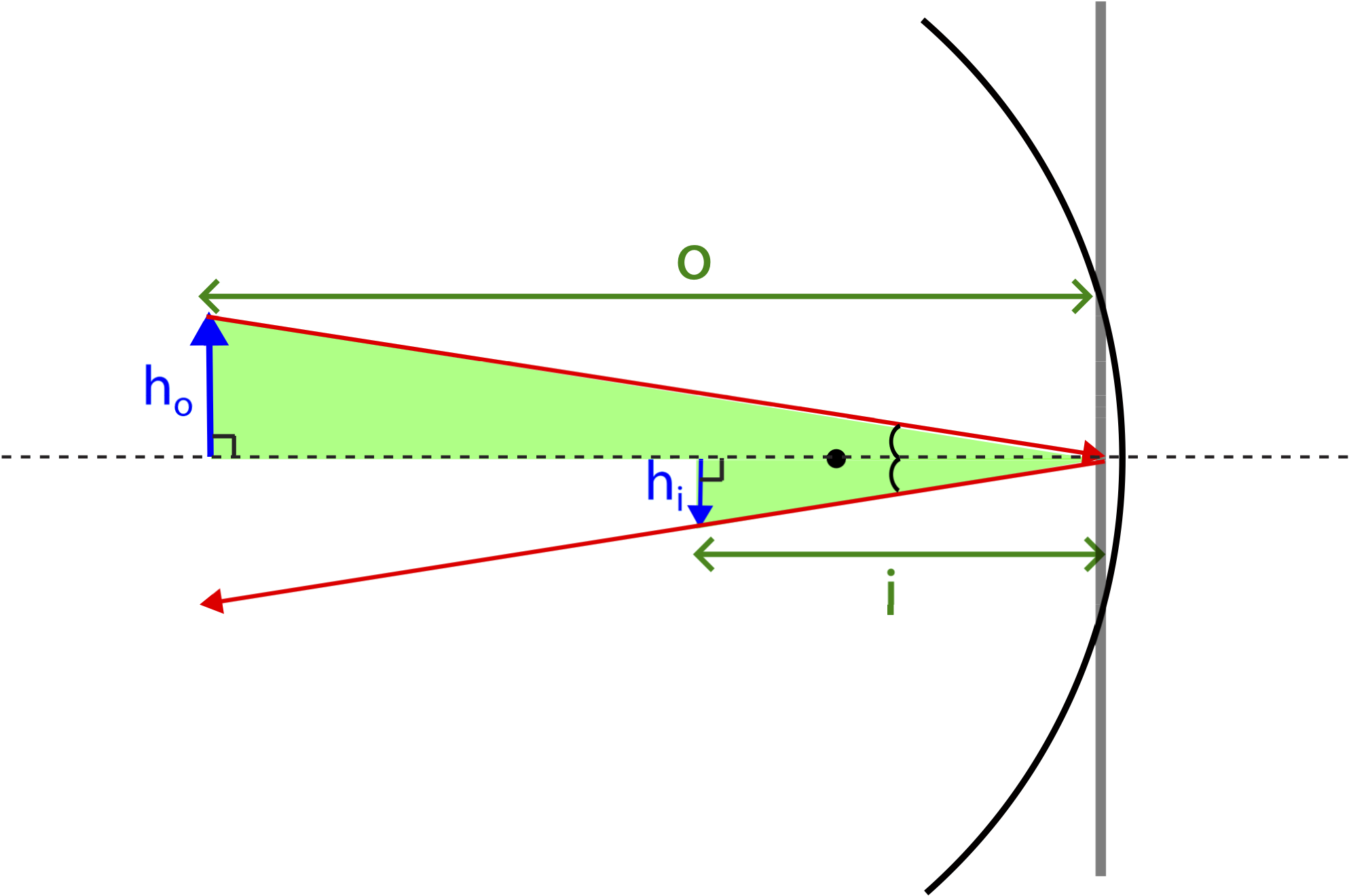
The figure below shows a real image formed by a concave spherical mirror. For the purpose of clarity only two principle rays are shown in the figure. The height of the object is labeled as \(h_o\), while the height of the image is marked \(h_i\). The horizontal distance from the object to the mirror is the object distance, o, and the distance from the image to the mirror is the image distance, i.
Figure 10.3.4: Deriving Equations for a Concave Spherical Mirror

Since we are using the small angle approximation (we assume that all distances are close to the optical axis), the mirror can be approximated as flat where light is reflected, as shown by the bold vertical line. This helps us relate these distances using the triangles shown in the figure. The two light pink triangles are similar, since they are both right triangles and share the same angle as marked. Using the property of similar triangles we get the following relationship:
\[\dfrac{h_o}{h_i}=\dfrac{o-f}{f}\]
The two turquoise triangles are similar as well. Using the same property of similar triangles we obtain another relationship for the ratio of heights:
\[\dfrac{h_o}{h_i}=\dfrac{f}{i-f}\]
Since the left-hand sides of the two equations above are the same, so we can set the right-hand sides equal to each other:
\[\dfrac{o-f}{f}=\dfrac{f}{i-f}\]
With some algebraic manipulations of the equation above we can to obtain the desired relationship between the focal length, the object distance, and the image distance:
\[\begin{array}{c}f^2=oi-of-if+f^2\\oi=f(o+i)\\\dfrac{1}{f}=\dfrac{o+i}{oi}\end{array}\]
Rewriting the above result in fractional form we arrive at the following (small angle) mirror equation:
\[\dfrac{1}{f}=\dfrac{1}{o}+\dfrac{1}{i}\label{mirror-eq}\]
Notice that when the object is placed exactly at the focal point, \(o=f\), the equation tells us that the image is formed at infinity. This result comes directly from the property of the focal point of a spherical mirror, all parallel rays reflect through the focal point. Due to the symmetry of the law of reflection, this implies that all rays that originate at the focal point when the object is placed there will be reflected parallel to the optical axis, placing the image at infinity.
Something interesting happens when the object is placed between the mirror and the focal point, \(o<f\). Equation \ref{mirror-eq} tells us that the image distance becomes negative since \(1/f<1/o\). The animation below shows ray tracing with two principle rays shown for the scenario of an object placed between the mirror and the focal point. Since the object is to the right of the focal point and the center of curvature, the principle rays that would be going through those points to reach the mirror are now the rays that are coming from the direction of the these two points toward the mirror. The red dashed lines on the side of the mirror in the animation are to stress that the rays are lined up with \(f\) and \(C\). The last principal ray, one that travels parallel to the optical axis and reflects through the focal point, is not shown in this animation. Thus, the reflection of these rays is dictated by the same rules, the ray lined up with the focal point will reflect parallel to the optical axis, and the one lined up with the center will reflect back along the same line.
Figure 10.3.5: Principal Rays for an Object Close to a Concave Spherical Mirror
The big difference between the refected rays in this animation and those in Figure 10.3.3 is that the reflected rays detected by the observer no longer intersect. Instead, we find that they do cross each other behind the mirror when traced behind the mirror. The rays are not physically present behind the mirror, as indicated by the dashed lines, so the image formed is a virtual image, as described by the plane mirror at the start of this section. The image is also upright and enlarged, as opposed to inverted and reduced in size as in Figure 10.3.3.
Mathematically, the distinction between a real image and a virtual image made by a mirror is in the sign of the image distance. We will define a convention that distances in front of the mirror are always positive. Thus, the focal length and the object distance for the concave mirror are positive. This results in the image distance for an image formed in front of the mirror will always be positive, while the image distance for an image formed behind the mirror will be negative. This comes directly from Equation \ref{mirror-eq}. Since both \(f>0\) and \(o>0\), the \(1/i\) is negative when \(1/f<1/o\) or \(o<f\) which is exactly the case in Figure 10.3.5 of an object placed between the focal point and the mirror. On the other hand, when \(o>f\) Equation \ref{mirror-eq} guarantees that the image distance will be positive.
Convex Mirrors
What if the other side of the concave mirror was reflective, the side that curves away? This results in another type of spherical mirror, known as the convex mirror, as shown below. In this case incoming parallel rays from a distance object will diverge from each other when reflected, precisely because of the "curving out" shape of this mirror.
Figure 10.3.6: Convex Mirror
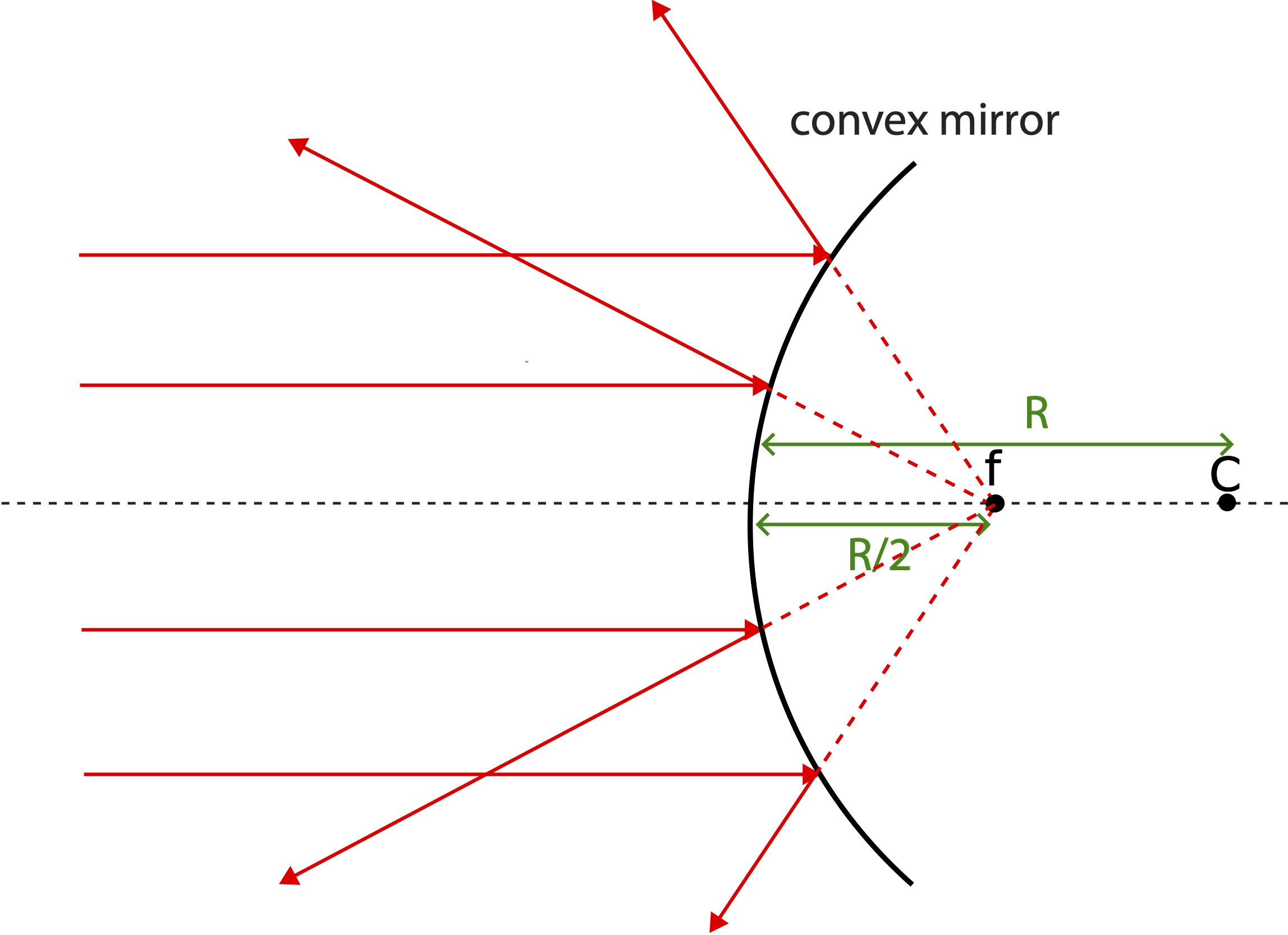
The convex mirror also has a radius of curvature, \(R\), defined as the distance from the mirror to the center of the partial spherical shell. Except, in this case it is on the opposite side of the mirror due to its shape. We also notice that although the parallel incoming rays do not converge on the side of the mirror, when traced back, they meet at one specific point (as before, this is valid within the small angle approximation). We define this point as the focal point of a convex mirror. The focal length has the same relationship to the center as a concave mirror, \(f=R/2\). However, since the the focal point does not focus physical rays, it is a virtual focal point. The same Equation \ref{mirror-eq} applies to convex mirrors.
As we did for concave mirrors, we can define three principle rays for a convex mirror. These are depicted in the animation below and described below:
- Principle ray #1: incoming ray parallel to the optical axis will reflect away from the focal point.
- Principle ray #2: incoming ray moving toward the focal point will reflect parallel to the optical axis.
- Principle ray #3: incoming ray moving toward center of curvature will reflect straight back.
Figure 10.3.7: Principal Rays of a Convex Spherical Mirror

As the animation shows the reflected rays will not converge in front of the mirror but will cross behind the mirror when traced back, forming a virtual upright image. In fact, a convex mirror will always make a virtual image of an object in front of the mirror. Using the sign convention defined when describing a concave mirror, the focal length will be negative for a convex mirror, since it is located behind it. From Equation \ref{mirror-eq} we can see that when the focal length is negative (\(f<0\)) the image distance will always be negative (\(i<0\)) since the object distance is always positive when an object is placed in front of the mirror (\(o>0\)).
Below is the summary of the important sign conventions:
- distances measured to a location in front of the mirror are positive.
- distances measured to a location behind the mirror are negative.
- object distances are positive, \(o>0\).
- focal lengths of concave mirrors are positive, \(f>0\).
- focal lengths of a convex mirrors are negative, \(f<0\).
- image distances for real images are positive, \(i>0\).
- image distances for virtual images are negative, \(i<0\).
Magnification
We also want to mathematically analyze the size of images relative to the size of objects. The magnification, M, is defined as:
\[M=\dfrac{h_i}{h_o}\]
where \(h_i\) is the height of the image, and \(h_o\) is the height of the object. Similar to distinguishing between real and virtual images, we want to distinguish mathematically upright from inverted images. We do this by assigning a sign to the heights of objects and images. If we define the location of the optical axis as zero height, then any distance above the axis is positive, and a distance below the axis is negative. When a concave mirror creates a real image, it is inverted, as seen in Figure 10.3.3. The height of the image is negative since the inverted image is below the optical axis, resulting in negative magnification. On the other hand, when a mirror makes a virtual image which is upright, as seen both in Figure 10.3.5 and Figure 10.3.7, the magnification is positive since both the object and image are above the optical axis and have positive heights.
The magnitude of magnification tells us about the relative size of the image to the object. If the size does not changes, as for the plane mirror in Figure 10.3.1, then the magnification is one (\(M=1\)), since the height of the object equals to the height of the image. If the image is larger than the object as in Figure 10.3.5, the object is magnified, and the absolute value of magnification is greater than one, since \(|h_i|>h_o\). If the image is smaller than then object, as in Figure 10.3.3, the object is demagnified, and the absolute value of magnification (ignoring the image orientation) is less than one, since \(|h_i|<h_o\).
Another interesting feature is the relationship of magnification to object and image distances, which can be demonstrated with a simple geometric argument. Consider the following triangles highlighted in Figure 10.3.8 below for a concave mirror creating a real image. To generate these triangle we used another "special ray" which is not one of the three principle rays. Since the optical axis (dashed horizontal line) goes through the center of curvature, it hits the mirror perpendicular to its surface. In other words, for the ray originating from the object below, the optical axis is the normal to the surface of the mirror. Thus, the reflected ray, that must goes to through the image, makes the same angle with the normal, according to the law of reflection. Therefore, since both triangles are right triangles and share another common angle, they are similar triangles. Thus, the ratio of the heights must equal to the ratio of horizontal distances marked.
Figure 10.3.8: Magnification Relationships
We just need to be careful about signs, since we defined the height of the image to be negative in this scenario. Thus, the ratio \(h_i/h_o<0\) by convention, but the ratio \(i/o\) is positive due to the sign conventions we established for object and image distances. In order to be consistent, we then define the relationship of magnification to object and image distances in the following way:
\[M=\dfrac{h_i}{h_o}=-\dfrac{i}{o}\]
where the minus sign in the equation assures the consistency of sign conventions. We can conclude by using the above equation, that for a positive object and image distance the magnification will be negative resulting in an inverted image, and for a positive object distance and a negative image distance, the magnification is positive resulting in an upright image.
Here is a summary of magnification sign and magnitude conventions:
- inverted images have negative magnification, \(M<0\).
- upright images have positive magnification, \(M>0\).
- magnified images have a magnitude of magnification greater than one, \(|M|>0\).
- demagnified images have a magnitude of magnification less than one, \(|M|<0\).
Example \(\PageIndex{2}\)
A spherical shell is reflective on both sides. When the reflection of an object is viewed on the convex side, the image is 40% of the size of the object. If the shell is now turned around so that the reflection is viewed on the concave side, determine the size of the image (compared to the object), and whether the image is upright or inverted. Assume that the distance between the shell and object are unchanged after the shell is rotated.
- Solution
-
Since we are working with one spherical shell where both side are reflective, the concave and convex sides will have the same radius of curvature and the same magnitudes of the focal lengths, except the concave side with have a positive focal length, while for the convex side the focal length will be negative. The object distance in this problem is the same for both the convex and concave sides. Since we know the magnification of the object when the convex side is used, we can relate the focal length to the object distance, then use this information to find the image distance in terms of object distance when the concave side is used.
Starting with the given information. The magnification when the convex side is used is:
\[M=-\dfrac{i}{o}=0.4=\dfrac{2}{5}\Rightarrow i=-\dfrac{2}{5}o\nonumber\]
The magnification is positive since convex mirror can only make virtual upright images.
Solving for the focal length in term of the object distance:
\[\dfrac{1}{f}=\dfrac{1}{o}+\dfrac{1}{i}=\dfrac{1}{o}-\dfrac{5}{2o}=-\dfrac{3}{2o}\nonumber\]
One check that there was no sign error is that the focal length for a convex mirror came out negative. The focal length when the concave side is used is then \(f=\dfrac{2}{3}o\). Using this to find the image distance with the concave side facing the object:
\[\dfrac{1}{i}=\dfrac{1}{f}-\dfrac{1}{o}=\dfrac{3}{2o}-\dfrac{1}{o}=\dfrac{1}{2o}\Rightarrow i=2o\nonumber\]
Calculating the magnification:
\[M=-\dfrac{i}{o}=-\dfrac{2o}{o}=-2\nonumber\]
Thus, the image is inverted and is double the size of the object.