
10.6: Lenses

( \newcommand{\kernel}{\mathrm{null}\,}\)
Lenses
In the previous couple of sections we saw that the law of reflection helps us understand how mirrors create images. In this section we will use the law of refraction to understand how another type of optical device, a lens can create an image. Instead of reflecting light like a mirror, a lens bends light, governed by the law of refraction, as it travels through a transparent material. There are numerous applications to lenses, the most common being corrective lenses uses in glasses to correct vision problems. In addition, lenses are used in technologies such as cameras, telescopes, and microscopes.
Converging Lenses
There are two types of lenses we will focus on. First type is a converging lens, which converges light upon refraction analogous to a concave mirror which converged light upon refection. The figure below show a particular shape of the converging lens, often called a convex lens, due to its shape.
Figure 10.6.1: Focal Point of Converging Lens

When parallel incoming light originating from a distance object or a laser refracts through the lens, the rays all converge to a single point, the focal point of the lens. You can see how this arises from refraction by following the bending of the rays twice. There are two refractions that occur, first rays travel from air to the glasslike material which bends light toward the normal. The second refraction occurs at the second boundary when the ray inside the lens refracts back into the air, this time bending away from the normal as it travels from a material of higher to lower index of refraction. This particular convex shape causes all the rays to converge to one point on the other side of the lens.
Unlike mirrors which have one reflecting side, lenses are perfectly symmetric. In other words, if you take the lens above and rotate it by 180o, the rays would converge to the same focal point. It's equivalent to saying that if you send rays from a distance object located on the right of the lens in the diagram above, the ray would converge to a point on the left, the same distance from the lens as the focal point on the right. Thus, unlike mirrors that have one unique focal point, lenses have two focal points on each side of the lens.
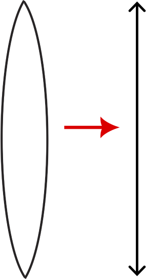
To simplify having to apply refraction twice, at each boundary we use the thin-lens approximation, which assume that the lens is infinitesimally thin compared to all other distances involved. Thus, we can assume that refraction only occurs once. Below is the symbol that we use to represent a converging lens in the thin-lens approximation.
Figure 10.6.2: Thin Lens Symbol for a Converging Lens
Now we would like to use ray tracing to determine the type of images a converging mirror makes. As for mirrors, we establish three principle rays for a converging lens. The principle rays are described and depicted in the animation below.
The three principle rays are:
- Principle ray #1: incoming ray parallel to the optical axis will refract through the far focal point.
- Principle ray #2: incoming ray that goes through the near focal point will refract parallel to the optical axis.
- Principle ray #3: incoming ray that goes through the center of curvature will follow a straight path as it goes through the lens.
Although the animation below shows the entire shape of the lens, it is clear that only one refraction is demonstrated using the central vertical dashed line to represent the thin lens approximation. In this animation an object placed further from the lens than the focal point creates a real, inverted, and de-magnified image on the other side of the lens. The image is real since it is physical rays that go through the lens and converge on the other side.
Figure 10.6.3: Ray Tracing for a Converging Lens, object outside the focal point
These three principle rays change slightly when the object is placed closer to the lens than the focal point as shown in the animation below.
Figure 10.6.4: Ray Tracing for a Converging Lens, object inside the focal point

In this case, the rays do not converge as they refract through the lens. However, when traced back the appear to meet at a location in front of the lens (same side as the object), creating a virtual, upright, and magnified image.
We will not cover the derivations for lenses, but interestingly, when we use the thin-lens approximation, the same exact equations that emerged when using the small-angle approximation for mirrors applies to thin lenses:
1f=1o+1i; M=hiho=−io
We will stick with the same convention as for mirrors: an optical device whose focal point is real will have a positive value for the focal length, such as the converging lens. Since object distances by convention are positive, this implies the image distance is positive for the scenario in Figure 10.6.3: o>f implies 1/f>1/o resulting in i>0. When the object is placed closer than the focal point as in Figure 10.6.4 the image distance becomes negative: o<f implies 1/f<1/o resulting in i<0. Another way of convincing yourself about the sign of the image distance is by looking at magnification. Since the real image in Figure 10.6.3 is inverted magnification has to be negative, resulting in positive image distance. On the contrary, for a virtual image, the magnification is positive, which means that the image distance in Equation ??? must be negative.
We conclude that the image distance is positive when it is real and formed on the other side on the lens. For concave mirrors, image distance was positive on the same side as the object when the image was real. Thus, the best way to remember the sign of the image distance is by thinking in terms of the image being real, implying i>0, or virtual which gives i<0.
Diverging Lenses
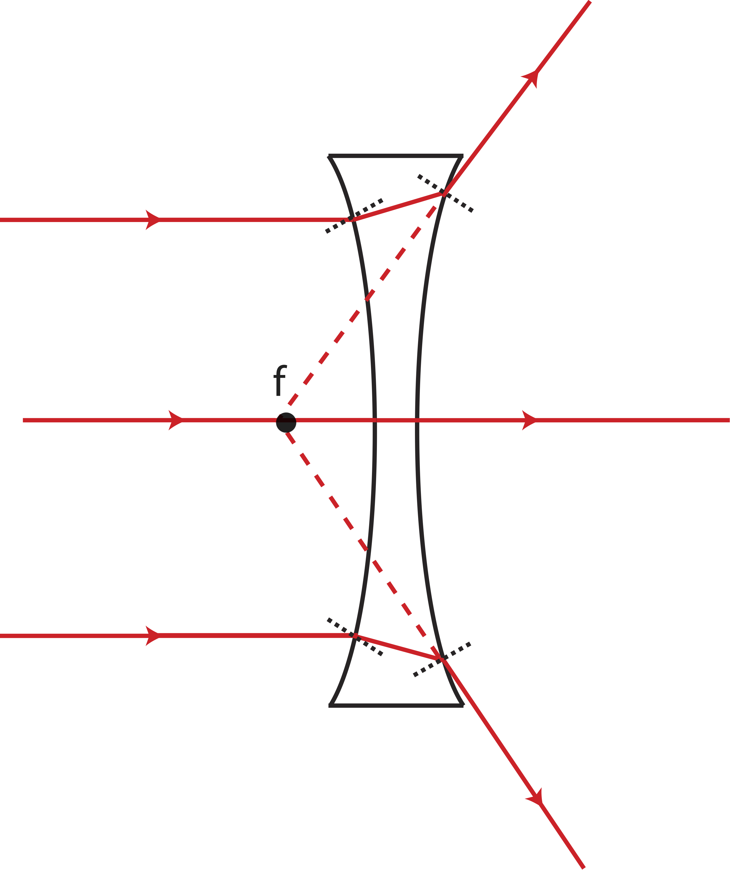
The analog to a convex mirror, is a diverging lens, also known as the concave lens, because of its shape shown below. When incoming parallel rays refract through a concave lens, they diverge away from each other on the other side of the lens. However, when traced back to the side of the lens from which the rays were incoming, we find they meet at a specific point. Thus, for diverging lenses the focal points are virtual, and will be negative, f<0, like the focal point for a convex mirror. As for converging lenses, diverging lenses have two focal points, one on each side of the lens.
Figure 10.6.5: Focal Point of Diverging Lens
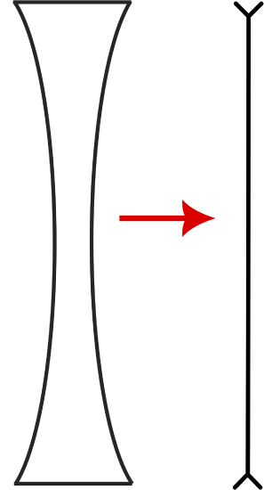
The symbol for the thin-lens approximation of a diverging lens is shown in the figure below.
Figure 10.6.6: Thin Lens Symbol for a Diverging Lens
When assuming the thin-lens approximation we only consider refraction one time. The three principle rays for a diverging lens are described and depicted below:
- Principle ray #1: incoming ray parallel to the optical axis will refract away from the near focal point.
- Principle ray #2: incoming ray that goes toward the far focal point will refract parallel to the optical axis.
- Principle ray #3: incoming ray that goes through the center of curvature will follow a straight path as it goes through the lens.
Figure 10.6.7: Ray Tracing for a Diverging Lens
The animation above shows a diverging lens making an upright, virtual, and de-magnified image in front of the lens. From Equation ???, we can see that diverging lenses will always form virtual images, since f is negative and o is positive. In addition, you can show using Equation ??? that the image distance will be always closer to the lens than the object, |i|<o. This result also implies that the image will always be de-magnified since |i|/o<1.
Example 10.6.1
Below is a picture of two arrows. One of them is an object and one is an image. The heights and the distance between the two arrows are drawn to scale (each grid represents 1 cm in distance).
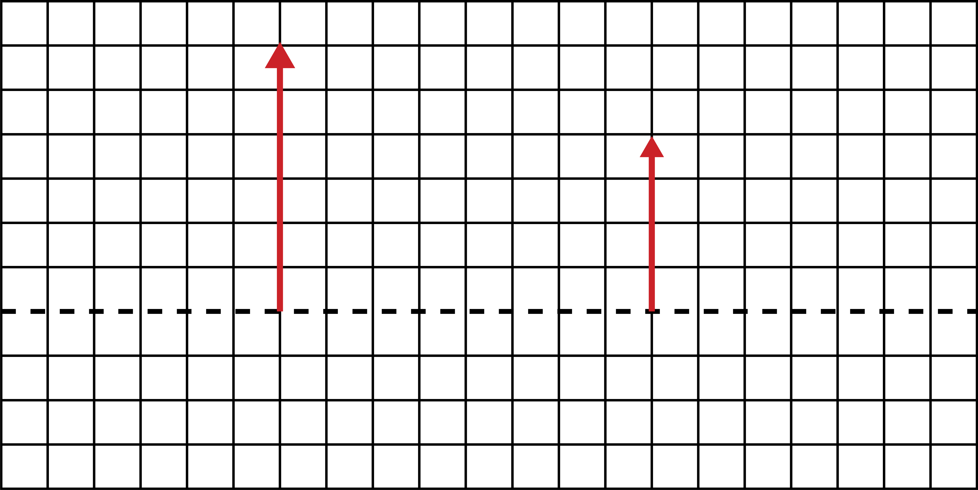
1. An optical device (a spherical mirror or a lens of either type) is placed in between the two arrows, resulting in the shorter arrow being the image.
a) Is this a mirror or a lens and which type?
b) Calculate the distance of the optical device from the object.
c) Determine the focal length of the optical device.
2. You now use a converging lens. Determine which arrow is the image and which one is the object. Is the lens to the right, in between, or to the left of the two arrows?
- Solution
-
1. a) Since both the object and the image are upright, the image must be virtual. Only a mirror produces virtual images on the other side of the object. Since the magnification is less than one, the mirror must be convex.
b) From the diagram, we can find the distance between the object and the image is:
o+|i|=8cm
The magnification can also be measured from the diagram:
M=hohi=46=23=−io
This results in the following relationship between image and object distances:
|i|=23o
Plugging this back into the first equation:
o+23o=53o=8cm→o=4.8cm
c) The image distance is negative:
i=−23×4.8cm=−3.2cm
Plugging into the mirror equation:
f=(14.8−13.2)−1=−9.6cm
2. When a converging lens produces a virtual image, the image is magnified. Thus, the taller arrow is the image and the shorter one is the object. Also, the object must be closer to the lens than the image, o<|i|, to give a negative image distance since the focal length is positive. Thus, the lens must be placed to the right of the two arrows, closer to the smaller arrow which is the object.
Shown below are two identical objects (same size and orientation) which are 5 cm apart. A lens is placed 3 cm to the right of object 1. You observe that both images formed of the two objects are at the same location.
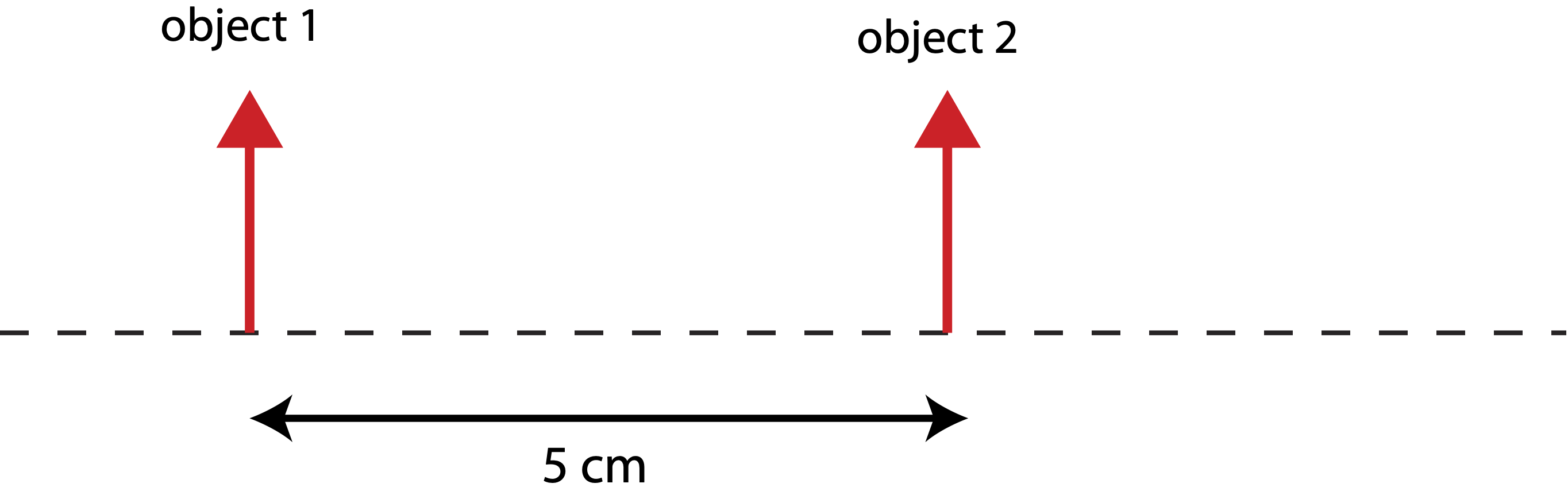
a) Determine the type of lens you have.
b) Calculate the location of the images in terms of distance to the right or left from object 1.
c) Determine the focal length of the lens.
d) Are the two images formed the same size? If not, which one is bigger?
- Solution
-
a) For both images to be at the same location, one image must be virtual and the other one real. Thus, the lens is converging.
b) The image of object 1 is real since the lens is further from this object, so the object must be placed outside the focal length. The thin-lens equation for this case is:
1f=13+1i
The image of object 2 is virtual, the image distance is negative, but its magnitude is the same as for the image of object 1:
1f=12−1|i|
Setting the two equations equal and solving for i we get:
13+1i=12−1i
i=12cm
The images are 15 cm to the right of object 1, 12 cm to the lens and another 3 cm to object 1.
c) Solving for focal length using the first equation in part b):
1f=13+112=512→f=2.4cm
d) Since M=−i/o and the image distance is the same for both, the one with the smaller object distance will be bigger, which is the image of object 2.