
3.5: Thin Film Interference


- Last updated
- Nov 8, 2022
- Save as PDF

( \newcommand{\kernel}{\mathrm{null}\,}\)
The Basic Idea
We have already seen three physical systems that result in interference patterns. While they all result in different patterns, they all function in pretty much the same way: A single wave is broken into multiple in-phase wavelets à la Huygens's principle, and these wavelets interfere with each other after traveling different distances to a position on a screen. Here we will see another interference phenomenon, and this one is also based on two waves traveling different distances, but this comes about due to reflection rather than diffraction.
An important element to this is that waves that strike a surface of a new medium partially reflect and partially transmit. This allows for the possibility that a single incoming wave can result in two waves being reflected off a thin, transparent film. Part of the wave reflects off the front surface of the film, and the other part off the rear surface of the film. These two reflected waves both come away from the film in the same direction, but they travel different distances in the process, because one of them traverses the thickness of the film twice, while the other does not. This difference can lead to destructive interference, meaning that no light is reflected!
This only scratches the surface of this phenomenon, however, because there are two other very important things going on that we have to take into account. The first of these is that waves which reflect off new media can possibly experience a phase shift of π if they reflect off a medium in which the wave moves more slowly (see Section 1.5 to review this phenomenon). The wave may make a phase shift at the front surface, the rear surface, both, or neither. As the phase difference between the two waves is the only factor that determines whether or not there is destructive interference, knowing whether or not each reflected wave has changed its phase by π is critical.
Figure 3.5.1 – Thin Film Destructive Interference
In the figure above, part of the incoming wave reflects off the front surface of the transparent film (the red wave), and the rest of it is transmitted into the film, after which it reflects off the rear surface (the blue wave). [Note that the different colors of these waves are used to distinguish them from each other, not to represent red and blue light – these waves have the same frequencies when they interfere.] These two waves come out together and interfere, but the red wave has a "head start" both in displacement (the thickness of the film), and in time – it is already propagating left while the incoming wave is still moving right, on its way to the rear surface. Of course, the film thickness can be adjusted to whatever we like, and in this particular case, it is one quarter of a wavelength of the light, which results in the destructive interference, as we can see in multiple ways.
To determine the interference of these two waves, we have to compute their total phase difference ΔΦ at the point when they superpose. So let's consider the position and time when they first encounter each other – at the front surface after the blue wave has reflected back to that point...
- That position is the starting point of the red wave, so xred=0. For the blue wave it is a position one quarter wavelength from its origin, so xblue=λ4, giving: Δx=xblue−xred=λ4.
- At the moment when they meet, the red wave has been propagating for one-half period (it propagates for the period of time that the incoming wave travels a quarter wavelength to the right, plus the time that the blue wave propagates a quarter wavelength back to the left), so tred=T2. The blue wave only travels a quarter wavelength by the time the two waves superpose, so it has been propagating for a quarter of a period: tblue=T4. This gives us a difference in time-of-propagation of: Δt=tblue−tred=−T4.
- Both waves experience a phase shift upon reflection, and come from a common incoming wave where they were in phase, so there is no difference in their phase constants: Δϕ=ϕblue−ϕred=0.
Putting all this together gives us the phase difference of the two waves when they rejoin (note that by choosing values of x to be positive measured to the left, the wave is moving in the positive direction, which means that the position and time parts of the phase must have opposite signs):
ΔΦ=2πλΔx−2πTΔt+Δϕ=2πλ(λ4)−2πT(−T4)+0=π
With the two waves out of phase by π, they interfere destructively:
I=Iocos2(ΔΦ2)=Iocos2(π2)=0
We can just as easily ignore the time element by choosing the zero time to be when the incoming wave first strikes the front surface. In this case, both waves start at the same moment (making Δt=0), but the wave that strikes the rear surface travels an extra half wavelength, since it has to make a round-trip across the film. Of course, the same answer results, and this is a somewhat simpler way to view the phase difference.
Note that a film thickness is not the only way that destructive interference can occur. If the thickness was instead three-quarters of a wavelength, then the round-trip distance for the transmitted wave is 1.5 wavelengths, and it once again emerges from the film out of phase with the reflected wave by π radians. We will summarize the effect of film thickness shortly, but there are a couple other loose ends we need to tie up first.
The Effect of Phase Shifts
In the example above, we mentioned the phase shifts that occurred at the boundaries of the media, but they didn't seem to take part in the calculation. This is because the same phase shift occurred at both boundaries. Suppose there was no third material involved (depicted in dark brown in the figure above), and that the film was by itself, surrounded on both sides with the exterior medium (presumably air, but no necessarily). In this case, there would be a phase shift at the reflection with the front surface, but no phase shift at the rear surface. Then the blue wave in the figure would not emerge upside-down, and it would come out in phase with the red wave. Mathematically this is not hard to see, as the space (and time) parts of the phase difference calculation are unchanged, but now we have the blue wave starting with a different phase than the red wave: Δϕ=π. When we put this into the calculation of the phase difference, we find that the two waves emerge in phase. For the waves to emerge out of phase, the film thickness would need to be different. Specifically, a thickness of one-half wavelength (or some integer number of half wavelengths) will make the distance traveled a full wavelength, which would normally make them in phase, but one of the waves is phase-shifted by π, putting them out of phase by that amount.
Example 3.5.1
A thin film of glass is in flush contact with a thin film of transparent plastic. Light travels faster through the air than through the glass, and faster through the glass than through the plastic. Monochromatic light is shone on both sides of this combination (the same frequency of light on both sides), and there is a negligible amount light reflected from either side. If the two films are now separated slightly to allow for a small air gap between them, and we repeat the process with the same light, what will we see in the way of light reflections from the two sides?
- Solution
-
The only change that occurs with the separation is that the second reflection in both thin films is now off a surface in contact with air. This means there will be no phase shift at that reflection, since air has a lower index of refraction than either film. Before the separation, the second reflection within the plastic was off a faster medium (glass), so there is no change to the phase shift for the plastic, and the same interference as before (destructive) will result. But the second reflection for the glass film was previously off a slower medium (plastic), so changing that reflection so that it is off air will make it go from a π radian phase shift to no phase shift. With the film thickness the same as before, this means that light that previously emerged from the glass π out of phase with the first reflection is now in phase with it, so light will be seen reflected off the glass film.
Light in a Medium
There is one element of this phenomenon that we have not yet accounted for. Clearly the film thickness has to be just right for the timing of the two reflected waves to come out exactly π out of phase. But when it comes to timing, there is another consideration – the wave moving through the film is moving through a different medium than the wave that reflects off the first surface, which means the two waves are moving at a different speeds. Clearly this will have to play a role in the timing that leads to the interference effect. Let's have a look at the effects of media on the speed of light.
As we stated in Section 3.1, light will travel through a vacuum, and its maximum speed occurs through that (non)medium. When light propagates through other medium that is transparent to it, it slows down. Going into what physical attributes of the media go into slowing down the light and by how much is beyond the scope of this course, but generally the effect is boiled down to a single constant called the index of refraction. This constant (n) is dimensionless, and is a number greater than 1 which provides the speed of light through a medium in terms of the speed through the vacuum (c) according to:
v=cn
When we discussed what happens when a wave passes from one medium to another, we concluded that the frequency remains the same, and the wavelength changes along with the velocity. This means that if a light wave is traveling from a medium with index of refraction n1 to a new medium with index of refraction n2, then the unchanging frequency gives the following relationship between the two wavelengths:
f1=f2⇒v1λ1=v2λ2⇒cn1λ1=cn2λ2⇒n1λ1=n2λ2
Since the index of refraction is larger where the light travels slower, then light passing into a slower/faster medium will exhibit a reduction/increase in wavelength.
All we need to do to complete the analysis above is use the proper wavelength for the light within the film. That is, with two phase shifts, the film still needs to have a thickness of one quarter (or three quarters, or five quarters, etc.) of the wavelength of the light, but that wavelength must be as measured within the film. Putting it all together, destructive interference occurs when light is reflected off a thin film when the light reflected off the front and rear faces emerge π radians out of phase, which occurs under the following circumstances (the Greek letter τ is used for film thickness, to avoid confusion with the time variable):
phase shifts at only one surface:2τ=mλinfilmphase shifts at both or neither surface:2τ=(m−12)λinfilmm=1,2,…
Putting It All Together
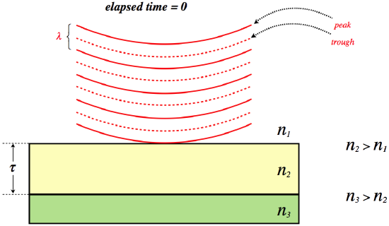
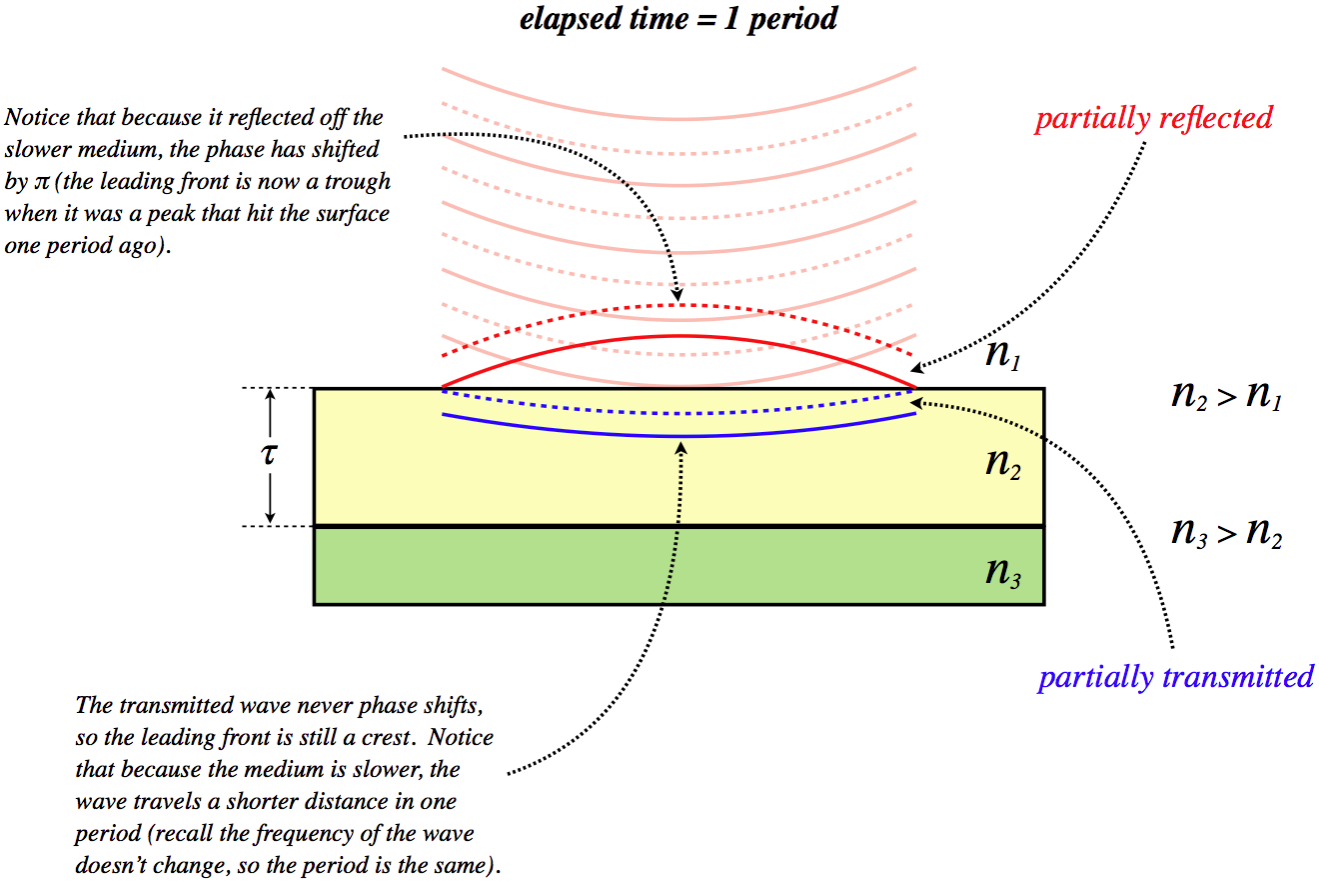
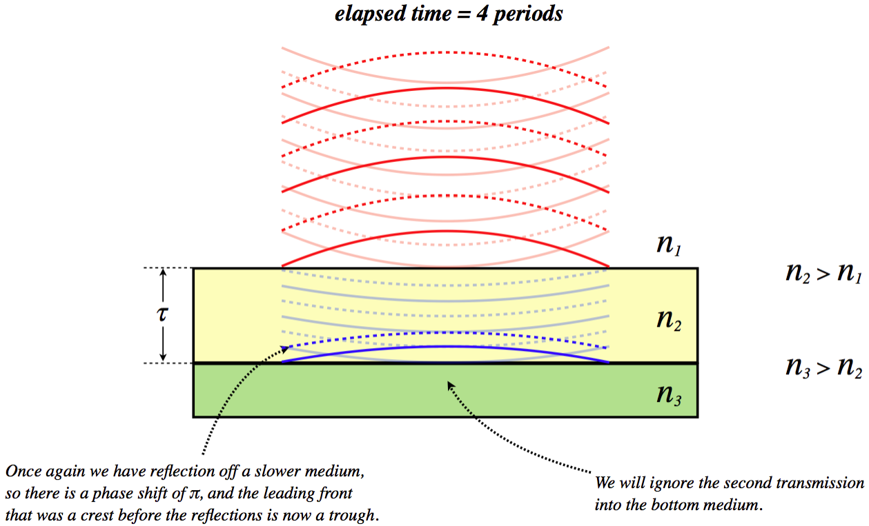
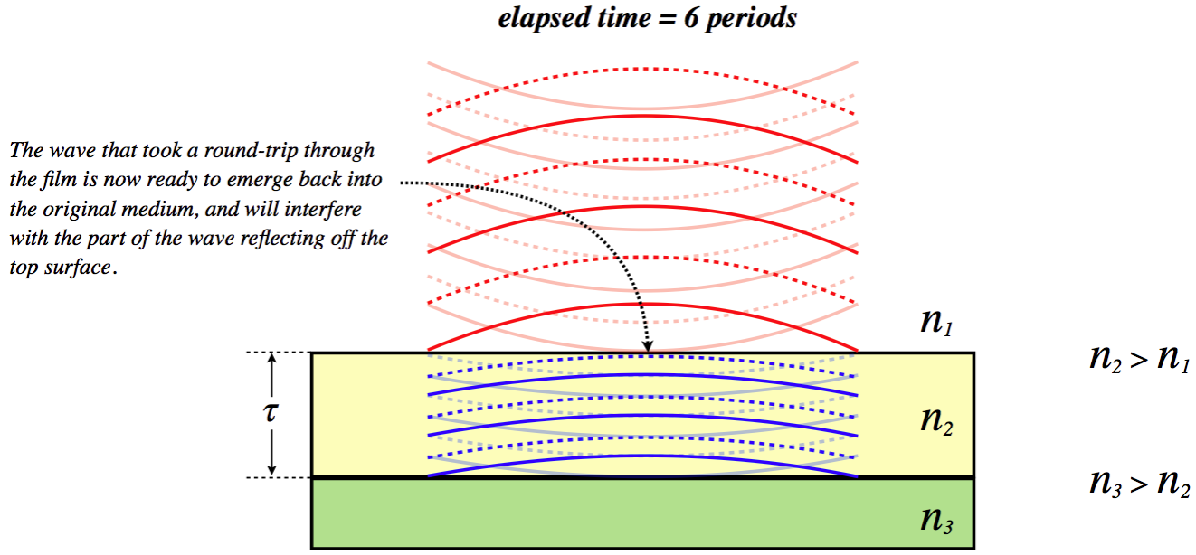
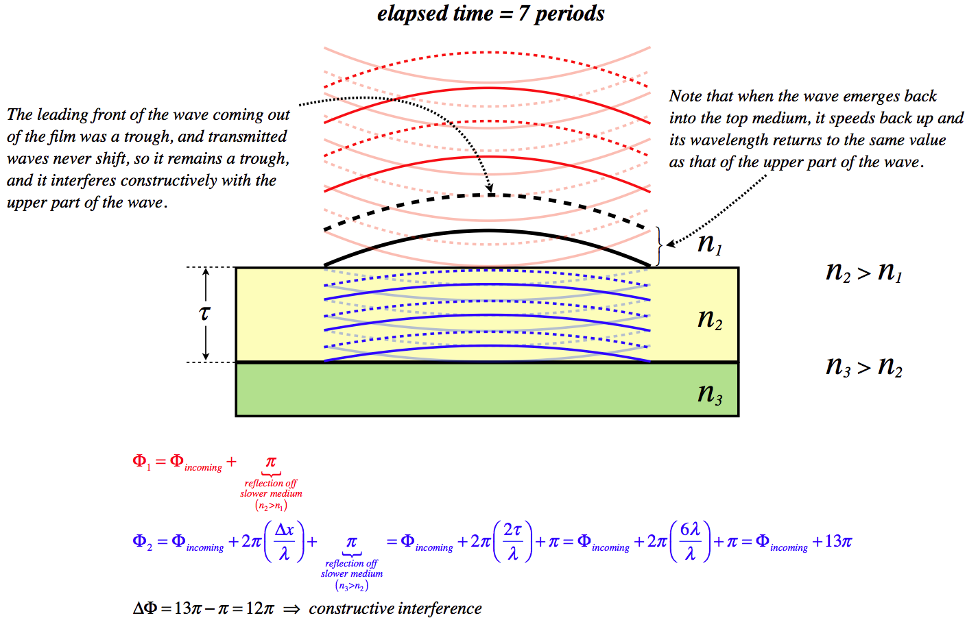
Let's put together a series of diagrams that reveal step-by-step what happens in thin film interference. There are several circumstances possible, but we will choose a film that has a thickness of three wavelengths of the light (as measured within that film), and assume the light is coming from a medium with a lower index of refraction, while behind the film is a medium with a higher index of refraction.
Figure 3.5.2 – Step-By-Step Thin Film Interference

Applications
This phenomenon can be observed and exploited in several ways. Let's start with observations...
Sunlight that reflects off a thin film of oil floating on a puddle of water will exhibit thin film interference in an interesting manner that comes about because the light is comprised of many wavelengths, and the film of oil is not uniform in thickness. The light will strike one part of the film, where the thickness happens to cause destructive interference for light of a certain wavelength. While it is not totally destructive for nearby wavelengths, they are out of phase by a number very close to π, which means that they are barely seen. So if the thickness happens to cause destructive interference for light near the red end of the spectrum, the reflected light will look more blue. At other points in the film, the thickness may cause the blue light to be canceled. The result is a reflection of a rainbow of colors. What is more, the variation in color tracks the thickness, so the observed rainbow swirls look like the grade lines on a topographical map, with each line of constant color indicating a different film thickness. These thickness variation rainbows can also be seen other thin films, such as soap bubbles.
A practical application of this effect are anti-glare films. When light strikes a thin film with air on both sides, if the film allows for no light to be reflected (i.e. all the reflected light destructively interferes), then conservation of energy requires that all of the light passes through the film to the other side. One place where one might want as much light as possible to pass through is a camera lens. Of course, cameras generally take photographs of objects illuminated by the entire spectrum of visible light, and it is impossible for thin films to create destructive interference for reflected light of all wavelengths at once. So generally the film chosen works for the middle of the spectrum (green light), which means that it doesn't work well for the ends of the spectrum (red and violet). With essentially only red and violet light able to be reflected by the film on a camera lens, the lens takes on a dark purple appearance.
The following example, while not a thin film problem, nevertheless incorporates the effect of a medium on interference patterns.
Example 3.5.2
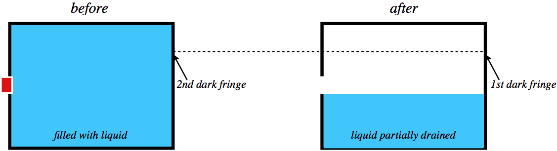
A chamber is filled with an unknown liquid, held within by a small rectangular hole in its side, as shown in the diagram below. The plug does not fit perfectly, and it allows light to pass through its top and bottom edges. Coherent monochromatic light is shone through these tiny gaps, and an interference pattern appears on the opposite wall of the chamber. The plug is then removed from the rectangular hole, and some of the liquid drains out. After it does so, a new interference pattern emerges above the level of the liquid (assume this occurs with negligible effect from the light reflected off the surface of the liquid). It is noted that the position of the first dark fringe of this new pattern exactly coincides with the position of the second dark fringe that appeared when the plug was still in place. Find the index of refraction of the unknown liquid. The index of refraction of air is approximately the same as a vacuum: nair=1.0.
- Solution
-
When the plug is in, the small slits at the outer edges that allow light to come in function as a double slit. The separation of these slits is the width of the hole, which we will call d. The angle at which the dark fringes occur for the double slit is given by the usual double slit relation, Equation 3.2.3. We see the second fringe, which corresponds to m=1, and the light is passing through the liquid, so the wavelength in this equation is the wavelength within the liquid:
dsinθ=(m+12)λliquid=32λliquid
The source of light remains unchanged, so whether the light is passing through the liquid or (after the chamber drains) the air, the frequency is the same. This means that the wavelength of the light through the liquid is related to the wavelength through the air according to:
nairλair=nliquidλliquid⇒λliquid=λairn,
where n is the index of refraction we are looking for.
When the plug comes out, the hole now becomes a single slit with the light traveling through air, and the gap size of this single slit (which we typically denote as a) is exactly equal to the double slit separation we used above: d. The first dark fringe for a single slit pattern corresponds to m=1 in the formula, so putting this (and a=d) into the formula gives us a relation between the wavelength of the light in air, the gap width, and the deflection angle:
asinθ=mλair⇒dsinθ=λair
Putting these three equations together, we find that all of the unknowns except for the index of refraction of the liquid cancel out, leaving simply n=1.5.