
2.4: Problem Solving
- Page ID
- 18390

\( \newcommand{\vecs}[1]{\overset { \scriptstyle \rightharpoonup} {\mathbf{#1}} } \)
\( \newcommand{\vecd}[1]{\overset{-\!-\!\rightharpoonup}{\vphantom{a}\smash {#1}}} \)
\( \newcommand{\dsum}{\displaystyle\sum\limits} \)
\( \newcommand{\dint}{\displaystyle\int\limits} \)
\( \newcommand{\dlim}{\displaystyle\lim\limits} \)
\( \newcommand{\id}{\mathrm{id}}\) \( \newcommand{\Span}{\mathrm{span}}\)
( \newcommand{\kernel}{\mathrm{null}\,}\) \( \newcommand{\range}{\mathrm{range}\,}\)
\( \newcommand{\RealPart}{\mathrm{Re}}\) \( \newcommand{\ImaginaryPart}{\mathrm{Im}}\)
\( \newcommand{\Argument}{\mathrm{Arg}}\) \( \newcommand{\norm}[1]{\| #1 \|}\)
\( \newcommand{\inner}[2]{\langle #1, #2 \rangle}\)
\( \newcommand{\Span}{\mathrm{span}}\)
\( \newcommand{\id}{\mathrm{id}}\)
\( \newcommand{\Span}{\mathrm{span}}\)
\( \newcommand{\kernel}{\mathrm{null}\,}\)
\( \newcommand{\range}{\mathrm{range}\,}\)
\( \newcommand{\RealPart}{\mathrm{Re}}\)
\( \newcommand{\ImaginaryPart}{\mathrm{Im}}\)
\( \newcommand{\Argument}{\mathrm{Arg}}\)
\( \newcommand{\norm}[1]{\| #1 \|}\)
\( \newcommand{\inner}[2]{\langle #1, #2 \rangle}\)
\( \newcommand{\Span}{\mathrm{span}}\) \( \newcommand{\AA}{\unicode[.8,0]{x212B}}\)
\( \newcommand{\vectorA}[1]{\vec{#1}} % arrow\)
\( \newcommand{\vectorAt}[1]{\vec{\text{#1}}} % arrow\)
\( \newcommand{\vectorB}[1]{\overset { \scriptstyle \rightharpoonup} {\mathbf{#1}} } \)
\( \newcommand{\vectorC}[1]{\textbf{#1}} \)
\( \newcommand{\vectorD}[1]{\overrightarrow{#1}} \)
\( \newcommand{\vectorDt}[1]{\overrightarrow{\text{#1}}} \)
\( \newcommand{\vectE}[1]{\overset{-\!-\!\rightharpoonup}{\vphantom{a}\smash{\mathbf {#1}}}} \)
\( \newcommand{\vecs}[1]{\overset { \scriptstyle \rightharpoonup} {\mathbf{#1}} } \)
\(\newcommand{\longvect}{\overrightarrow}\)
\( \newcommand{\vecd}[1]{\overset{-\!-\!\rightharpoonup}{\vphantom{a}\smash {#1}}} \)
\(\newcommand{\avec}{\mathbf a}\) \(\newcommand{\bvec}{\mathbf b}\) \(\newcommand{\cvec}{\mathbf c}\) \(\newcommand{\dvec}{\mathbf d}\) \(\newcommand{\dtil}{\widetilde{\mathbf d}}\) \(\newcommand{\evec}{\mathbf e}\) \(\newcommand{\fvec}{\mathbf f}\) \(\newcommand{\nvec}{\mathbf n}\) \(\newcommand{\pvec}{\mathbf p}\) \(\newcommand{\qvec}{\mathbf q}\) \(\newcommand{\svec}{\mathbf s}\) \(\newcommand{\tvec}{\mathbf t}\) \(\newcommand{\uvec}{\mathbf u}\) \(\newcommand{\vvec}{\mathbf v}\) \(\newcommand{\wvec}{\mathbf w}\) \(\newcommand{\xvec}{\mathbf x}\) \(\newcommand{\yvec}{\mathbf y}\) \(\newcommand{\zvec}{\mathbf z}\) \(\newcommand{\rvec}{\mathbf r}\) \(\newcommand{\mvec}{\mathbf m}\) \(\newcommand{\zerovec}{\mathbf 0}\) \(\newcommand{\onevec}{\mathbf 1}\) \(\newcommand{\real}{\mathbb R}\) \(\newcommand{\twovec}[2]{\left[\begin{array}{r}#1 \\ #2 \end{array}\right]}\) \(\newcommand{\ctwovec}[2]{\left[\begin{array}{c}#1 \\ #2 \end{array}\right]}\) \(\newcommand{\threevec}[3]{\left[\begin{array}{r}#1 \\ #2 \\ #3 \end{array}\right]}\) \(\newcommand{\cthreevec}[3]{\left[\begin{array}{c}#1 \\ #2 \\ #3 \end{array}\right]}\) \(\newcommand{\fourvec}[4]{\left[\begin{array}{r}#1 \\ #2 \\ #3 \\ #4 \end{array}\right]}\) \(\newcommand{\cfourvec}[4]{\left[\begin{array}{c}#1 \\ #2 \\ #3 \\ #4 \end{array}\right]}\) \(\newcommand{\fivevec}[5]{\left[\begin{array}{r}#1 \\ #2 \\ #3 \\ #4 \\ #5 \\ \end{array}\right]}\) \(\newcommand{\cfivevec}[5]{\left[\begin{array}{c}#1 \\ #2 \\ #3 \\ #4 \\ #5 \\ \end{array}\right]}\) \(\newcommand{\mattwo}[4]{\left[\begin{array}{rr}#1 \amp #2 \\ #3 \amp #4 \\ \end{array}\right]}\) \(\newcommand{\laspan}[1]{\text{Span}\{#1\}}\) \(\newcommand{\bcal}{\cal B}\) \(\newcommand{\ccal}{\cal C}\) \(\newcommand{\scal}{\cal S}\) \(\newcommand{\wcal}{\cal W}\) \(\newcommand{\ecal}{\cal E}\) \(\newcommand{\coords}[2]{\left\{#1\right\}_{#2}}\) \(\newcommand{\gray}[1]{\color{gray}{#1}}\) \(\newcommand{\lgray}[1]{\color{lightgray}{#1}}\) \(\newcommand{\rank}{\operatorname{rank}}\) \(\newcommand{\row}{\text{Row}}\) \(\newcommand{\col}{\text{Col}}\) \(\renewcommand{\row}{\text{Row}}\) \(\newcommand{\nul}{\text{Nul}}\) \(\newcommand{\var}{\text{Var}}\) \(\newcommand{\corr}{\text{corr}}\) \(\newcommand{\len}[1]{\left|#1\right|}\) \(\newcommand{\bbar}{\overline{\bvec}}\) \(\newcommand{\bhat}{\widehat{\bvec}}\) \(\newcommand{\bperp}{\bvec^\perp}\) \(\newcommand{\xhat}{\widehat{\xvec}}\) \(\newcommand{\vhat}{\widehat{\vvec}}\) \(\newcommand{\uhat}{\widehat{\uvec}}\) \(\newcommand{\what}{\widehat{\wvec}}\) \(\newcommand{\Sighat}{\widehat{\Sigma}}\) \(\newcommand{\lt}{<}\) \(\newcommand{\gt}{>}\) \(\newcommand{\amp}{&}\) \(\definecolor{fillinmathshade}{gray}{0.9}\)Next we are going to focus on elements of problem-solving. We have all the tools we need, so this will not involve any new physics, but the idea is to introduce you to some common themes that come up in physics mechanics problems.
Pulleys
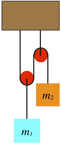
One of the favorite devices for physics problems is the pulley. As was stated in the description of the tension force, to start out we use the simplest model, which means we will assume that pulleys are massless and frictionless. Pulleys get especially interesting in situations like the following example, where at least one of the pulleys is able to move. The two blocks remain at rest in the system of ropes and pulleys shown in the diagram. Given this information, can you conclude how the two masses compare?
Figure 2.4.1 – Blocks Hanging from Multiple Pulleys
By now we know that when it comes to analyzing the forces present in a system, there is no better tool than the FBD. We begin there:
Figure 2.4.2 – FBD of the Block and Pulley
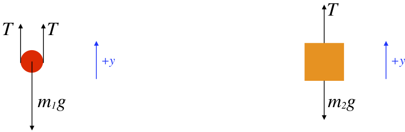
[We have taken the liberty of defining coordinate systems in our FBDs – up is the \(+y\)-direction for both – which we will need shortly.]
One might ask why there are two tension force vectors drawn for the pulley. The simplest answer is to consider what you would feel if you cut the rope on both sides of the pulley and held one end in each hand. Clearly you would feel both ends of the rope pulling down. Therefore by Newton's third law, both ends of the rope are pulling up on the pulley. With the pulley massless and frictionless, these two tension forces must also be equal, which explains why they are labeled the same. Note that the tension vector on the block is also labeled with the same variable name. This is because it is the same rope, and our assumption of massless, frictionless pulleys ensures that everywhere that we measure the tension for a single piece of rope, it will be the same.
Alert
If we were to draw the tension force vector pulling up on the right pulley, we would not be able to label it the same. Not all tension vectors in a single physical system are equal, just the magnitudes of all tension vectors derived from the same rope.
Another curious aspect of this FBD is the weight label of the left pulley. Technically, that force is acting on the block, and the block is pulling on the pulley. The pull on the pulley by the block happens to equal the weight of the block in this case, and the pulley has no weight of its own, so we are justified in taking this little shortcut. Another way to justify it is to treat the block + pulley as a single system, and the gravity force on the system is the force vector shown.
The next step in our analysis is to sum the forces for each object and apply Newton's second law, which in this case involves zero acceleration. In taking the sum of forces, we have to take care to correctly use our coordinate system:
\[ \left. \begin{array}{l} 0 = a_1 = \dfrac{F_{net \; 1}}{m_1} = \dfrac{2T - m_1 g}{m_1} \;\;\; \Rightarrow \;\;\; T = \dfrac{m_1 g}{2} \\ 0 = a_2 = \dfrac{F_{net \; 2}}{m_2} = \dfrac{T - m_2 g}{m_2} \;\;\;\; \Rightarrow \;\;\; T = m_2 g \\ \end{array} \right\} \;\;\; \Rightarrow \;\;\; m_1 = 2 m_2\]
Notice that the light weight \(m_2\) holds up the heavier one because the placement of the pulley allows us to use the tension from the same rope twice on the heavier mass. This trick can actually be repeated as many times as we like (the pulley can have multiple tracks in it), and this enables us to lift very heavy weights with very little force. This invention is called a block and tackle. They are used for sailing ships (the heavy sails and boom can be pulled tighter), lifting engine blocks, and many other applications.
Constraints
Next we take on a tricky concept known as constraints. A constraint is a condition that exists for a physical system that restricts how it can behave. What makes the concept "tricky" is that these ultimately play a mathematical role in the solution of the problem, but this role is often difficult to extract from the statement of the problem. Put simply, constraints relate variables in the problem to each other, providing additional equations (beyond Newton's second law) to work with. We have already seen an example of a constraint. It is the relationship between the friction force and the normal force. For kinetic friction this provides an equation that relates these two forces, while for static friction it sets an upper limit on the magnitude of friction for a given normal force.
One of the most common examples of a constraint is related to ropes moving through pulleys. This constraint relates the motion of one object to that of another when they are connected through a system of pulleys. Let us return to the system shown in Figure 2.4.1 and ask the following question: If the block \(m_2\) drops a distance \(\Delta y \), what happens to the block \(m_1\)?
First of all, it should be clear that \(m_1\) rises as \(m_2\) drops, so the only question is, how far? This may not be apparent at first, but think of it this way: When the pulley holding \(m_1\) moves up 1 unit, both segments of string going up from the pulley get shorter by 1 unit. These two units of string don't simply vanish, and in fact they are taken-up by the free end of the string, which is attached to \(m_2\). This means that as \(m_2\) drops a distance of \(\Delta y \), \(m_1\) must rise only half that far.
What does this say about the comparison of the speeds and accelerations of the two blocks? Well, they are required to move simultaneously, so every unit of length dropped by \(m_2\) is matched by a rise of \(m_1\) by half as much, which means that \(m_1\) always moves at half the speed and accelerates half as much as \(m_2\). If this system is not balanced (as it was above), then applying Newton's second law to both blocks includes two accelerations, but these are constrained to be related to each other by a factor of two, providing us with an additional constraint equation:
\[ 2\left| a_1 \right| = \left| a_2 \right|\]
What's with the absolute values, you ask? Well, these variables can have positive or negative values, and we must be careful when it comes to signs. in particular, we have to look at how our constraint relates to our choice of coordinate systems for the two blocks. In Figure 2.4.2, we chose "up" as the positive direction for both blocks. So we need to ask ourselves, "If one block experiences a positive displacement, what is the sign of the displacement of the other block?" In this case it's clear that the displacement of the two blocks have opposite signs. Therefore the constraint equation for the block accelerations is:
\[ 2a_1 = -a_2\]
Note that it is perfectly fine to set up different coordinate systems for the two blocks – each FBD is entitled to its own individual coordinate system. How the coordinate systems relate to each other affects the equation of constraint. So for example, if we had instead chosen downward to be the +\(y\)-direction for block #2 (but left upward as positive for the other block), then there would be no need for the minus sign in the constraint equation – positive displacements of one block correspond to positive displacements of the other block. We see that there is therefore no "correct" choice of coordinate system, but we must take care when the time comes to combine the equations from the two FBDs that the constraint equations relate the variables correctly. We will see an even more striking example of coordinate system choice in the next example.
Example \(\PageIndex{1}\)
The heights of the two blocks in the diagram below differ by 36cm. When they are released from rest, the higher block falls while the lower block rises. One of the blocks has a mass that is three times the mass of the other block, the pulleys are massless and frictionless, and the string doesn't stretch.
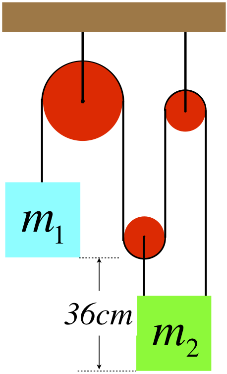
- Which is the heavier block? Explain.
- Find the distance that the lower block rises when the two blocks are aligned.
- Find the time it takes for the two blocks to be aligned.
- Solution
-
a. The tension exerted by the string threaded through the pulleys is the same everywhere, so there is three times as much tension force acting up on the lower block as there is up on the higher one. If the lower block was three times heavier than the higher block, then the system would be balanced, and neither mass could be accelerating. [You should try doing the math of part (c) with the masses the other way, and demonstrate for yourself that it the acceleration would have to be zero.] Given that the system is accelerating, it must be the higher block with the greater mass.
b. As the top block pulls the string down on one side of the large pulley, the same amount of string that is gained on the left side of the pulley is lost from the right side. The string on the right side of the large pulley is divided between the three segments holding up the other block. Therefore the lower block moves up one third as far as the higher block moves down. If the lower block rises a distance \(y\), then the higher block drops a distance \(3y\), and since they reach the same height, the sum of those changes is 36cm, which means the lower block rises a distance of \(y=9\)cm.
c. To find the the time it takes them to align, we need to use their accelerations. We know their relative accelerations already: The lower block accelerates at one third the rate of the higher block. We'll therefore call the higher block's acceleration "\(3a\)," making the lower block's acceleration equal to \(a\). But we need Newton's laws in order to go any further. FBD of the two systems involved look like this:
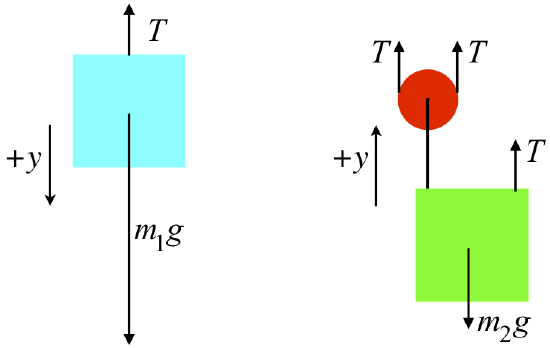
The higher mass is three times the lower mass, so we will call \(m_2\) simply "\(m\)," which makes \(m_1\) equal to \(3m\). Plugging everything into Newton's second law for both FBDs gives these equations:
\[ \left. \begin{array}{l} a_1 = \dfrac{F_{net \; 1}}{m_1} \;\;\; \Rightarrow \;\;\; 3a = \dfrac{-T + 3mg}{3m} \\ a_2 = \dfrac{F_{net \;2}}{m_2} \;\;\; \Rightarrow \;\;\; a = \dfrac{3T - mg}{m} \\ \end{array} \right\} \;\;\; \Rightarrow \;\;\; a = \frac{2}{7} g \nonumber \]
With the acceleration of the lower block, the distance it travels, and the fact that it starts from rest, we can compute the time it takes to make the trip:
\[ y = v_o t + \frac{1}{2}at^2 \;\;\; \Rightarrow \;\;\; t = \sqrt{ \dfrac{7y}{g}} = \boxed{0.25s} \nonumber \]
Inclined Planes
Pulleys (and in particular the block & tackle) are an example of something often referred to as a simple machine. This is because we can use such a device to lift a heavy weight with a force less than the weight itself. Another example of a simple machine is the inclined plane. These devices also allow one to accomplish the task of raising a heavy object to a higher position using less force than would be necessary in a direct lift. The main feature of problems involving inclined planes is dealing with the coordinate system used for the object on the inclined plane. Let’s look at an example. As usual, we start with the very simplest of examples, and complicate it as we go – a block of mass \(M\) on a frictionless plane inclined at an angle \(\theta\):
Figure 2.4.3 – Block on an Inclined Plane
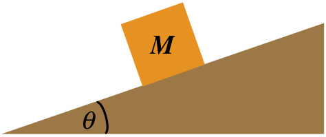
We begin our analysis, as always, with a free-body diagram. No FBD is complete without a choice of coordinate system, so we must choose one here. If we choose our coordinate system to be horizontal and vertical as we usually do, then when the block slides down the plane its acceleration will have both \(x\) and \(y\) components. This is fine of course, but it can be a bit cumbersome to work with. There is nothing sacred about the horizontal and vertical directions, so why not choose a coordinate system that is parallel and perpendicular to the plane?
Figure 2.4.4 – Coordinate System for an Inclined Plane
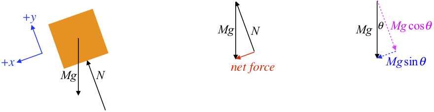
The middle diagram in Figure 2.4.4 shows the tail-to-head sum of the normal and gravity forces resulting in a net force parallel to and down the plane, as it should be, since we know that is the direction the block will accelerate. The right diagram shows the gravity force broken into its \(x\) and \(y\) components in the chosen coordinate system (you should verify for yourself the geometry that leads to concluding that the angle in this diagram is the same angle that the incline makes with the horizontal). Note that since the block does not accelerate perpendicular to the plane, we can conclude that \(N=Mg\cos{\theta}\). Also it's clear that the net force is the \(x\)-component of the gravity force, resulting in an acceleration down the plane of simply \(a=g\sin{\theta}\).
Suppose we wanted to raise this block to some new height. To get it moving up the plane, we would need to apply a force that exceeds the net force shown above, which is less than the force we would have to apply to lift it straight up. Like the case of the block & tackle, this "simple machine" helps us to get a job done while using less force than is required if it is done more directly. In the case of the block & tackle, to raise the mass some distance, the other end of the rope had to be pulled a greater distance. In this case we see a similar thing – the distance we must push the block is the hypotenuse of the triangle in order to raise it the height of the vertical leg of the triangle. This is a common theme in simple machines – less force is required, but it must be applied over a longer distance. In the next chapter we will see why this is the case.
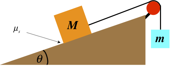
We can complicate this simple example considerably. The most natural adjustment is to incorporate friction. Because of the nature of the two types of friction, adding static friction (which enters as an inequality) can be particularly troublesome. To see why, let's consider the following problem:
The system depicted in Figure 2.4.5 shows two blocks that remain at rest which are attached by a massless string over a massless, frictionless pulley. The plane is inclined at an angle \(theta\) up from the horizontal, and its surface is rough (i.e. not frictionless). The mass of the hanging block is given, as is the angle of incline and the coefficient of static friction. From these quantities, determine the minimum possible value of the mass of the block on the plane.
Figure 2.4.5 – A Mechanical System
Starting (as always) with a FBD (including a coordinate system) for each block, we have:
Figure 2.4.6 – Free-Body Diagrams of Blocks
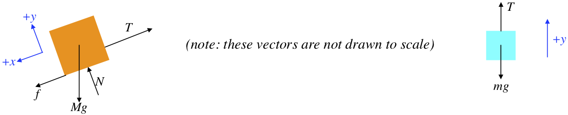
Let's take a moment to comment on the direction of the static friction force. Recall that a static friction force merely reacts to the "attempted" motion of the object along the surface. In this case, if the block was "trying" to slide down the plane, then the static friction force must be up the plane. Here it is drawn pointing down the plane, which means the other forces present must be such that they would accelerate it up the plane... How do we know this is the case? The answer lies in the statement of the question: We are looking for the minimum mass for the block on the plane. Imagine putting in a block whose mass balances the system. if a small mass is added to or subtracted from the block, the system may still remain at rest, as the static friction keeps the balance. If we add too much mass to that block, the static friction will reach its limit and the block will begin sliding down, while if we take away too much mass, it will slide up the plane. The static friction will oppose the intended motion, so for the minimum mass, the static friction force must point down the plane.
Alert
While we are able to determine the direction of the static friction for this problem, in many problems this is not possible. If you know that the static friction force is (or could be) present, just draw it in with either direction. When the problem is complete, if you solve for the value of this force, it will come out positive if you chose the correct direction, and negative if you did not. The FBD is just a tool, and in the end you end up with the answer, so don't waste energy worrying about getting the direction correct on the diagram.
Breaking the vectors into components in our chosen coordinate systems and applying Newton's second law (for zero acceleration) gives:
\[ \begin{array}{l} block\;on\;plane:\;\; \begin{array}{l} x - direction\;forces: \;\; 0 = a_x = \dfrac{f - T + Mg\sin{\theta}}{M} \\ y - direction\;forces:\;\; 0 = {a_y} = \dfrac{N - Mg\cos{\theta}}{M} \end{array} \\ hanging\;block:\;\;\; y - direction\;forces:\;\; 0 = {a_y} = \dfrac{T - mg}{m} \end{array} \]
Next, apply the constraint that relates the maximum static friction force (which occurs when the minimum mass is on the plane) and the normal force:
\[ f \le \mu_S N \;\;\; \Rightarrow \;\;\; (maximum \; f \; for \; minimum \; M) \;\;\; \Rightarrow \;\;\; f = \mu_S N\]
The rest is algebra with four simultaneous equations, the result of which is:
\[M_{min} = \frac{m}{\mu _S \cos \theta + \sin \theta }\]
We should now check to see if this answer makes sense. If the angle \(theta\) is \(90^o\), then both masses are hanging, and there is not friction force (because there is no normal force). For the system not to accelerate, the two masses must be equal. Plugging in \(\theta=90^o\) indeed results in \(M=m\). The \(\theta\ = 0^o\) case (a horizontal surface, where the normal force equals the weight of the block on the surface) will require that the friction force equals the weight of the hanging block. That is, we must have \(mg=f=\mu_S N=\mu_S Mg\;\; \Rightarrow \;\; m=\mu_S M\), which is what we get when we plug in zero for \(\theta\).
This problem could just as easily have asked for the maximum possible value for \(M\). It is left as an exercise for the reader to try this.
There was a lot involved with this problem, but the key is to take it one step at a time and follow the following prescribed steps:
- draw a diagram
- isolate the relevant objects and draw free-body diagrams for them
- choose coordinate systems for the diagrams that are convenient
- break forces into components in the coordinate system chosen
- sum the forces in the \(x\) and \(y\) directions and apply Newton’s second law for both directions
- apply the constraints
- solve the algebra
Example \(\PageIndex{2}\)
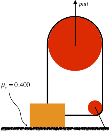
A rope is fastened to a 50.0kg block in two places and passes through a system of two pulleys, as shown in the diagram below. The block rests on a rough (coefficient of static friction is 0.400) horizontal surface. The bigger pulley is then pulled upward with gradually increasing force. Both pulleys are massless and frictionless, and the rope is also massless. The smaller pulley is fastened to the floor and the both pulleys are positioned such that the rope is perpendicular to the floor on one end and parallel to it on the other. When the pull force reaches a certain magnitude, the block just barely begins to slide to the right. Compute the magnitude of this pull force.
- Solution
-
This problem doesn't feature an inclined plane (though it could!), but it is a good example of the importance of following the prescription listed above. Start with the free-body diagrams and coordinate systems. The FBD of the smaller pulley will yield us nothing useful, so there are just two FBDs to draw. Note that the tension on the side of the block comes from the same rope as the tension on the top of the block, so they are equal:
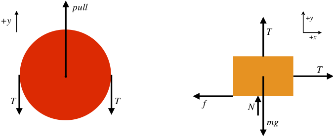
The block is not accelerating at all (nor is the pulley), so the sum of the forces in each of the \(x\) and \(y\) directions comes out to zero.
\[ \begin{array}{l} block:\;\; \begin{array}{l} x - direction\;forces: \;\; 0 = T - f \\ y - direction\;forces:\;\; 0 = T+N-mg \end{array} \\ pulley:\;\; y - direction\;forces:\;\; 0 = pull - 2T \end{array} \nonumber \]
If we have to pull "just hard enough" to get the block moving, then this occurs when the horizontal pull equals the maximum static friction force, which gives us a constraint equation:
\[ f = \mu_S N\nonumber\]
Note that the block will have to start sliding before it starts rising, because rising requires than the normal force equals zero, and it will slide when the static friction force is small-but-non-zero. Now solve the equations simultaneously to get:
\[ pull = \boxed{280N} \nonumber \]
Incorporating Motion
We’ve done two examples involving systems for which the acceleration is zero. But of course it’s possible that a problem could actually involve accelerating objects. Sometimes we are asked to find this acceleration, and other times the acceleration is a piece of information that is given. The acceleration can be given directly, or possibly it can be calculated in another way, perhaps from kinematics or if the motion is circular. Knowing something about the motion of the object falls under the “constraints” category, because the motion is specified (constrained), bringing in equations that don't result from Newton's second law. We'll look at an example that employs the steps to solving mechanics problems that also includes the added constraint of circular motion. Before we do, give the following example a try:
Example \(\PageIndex{3}\)
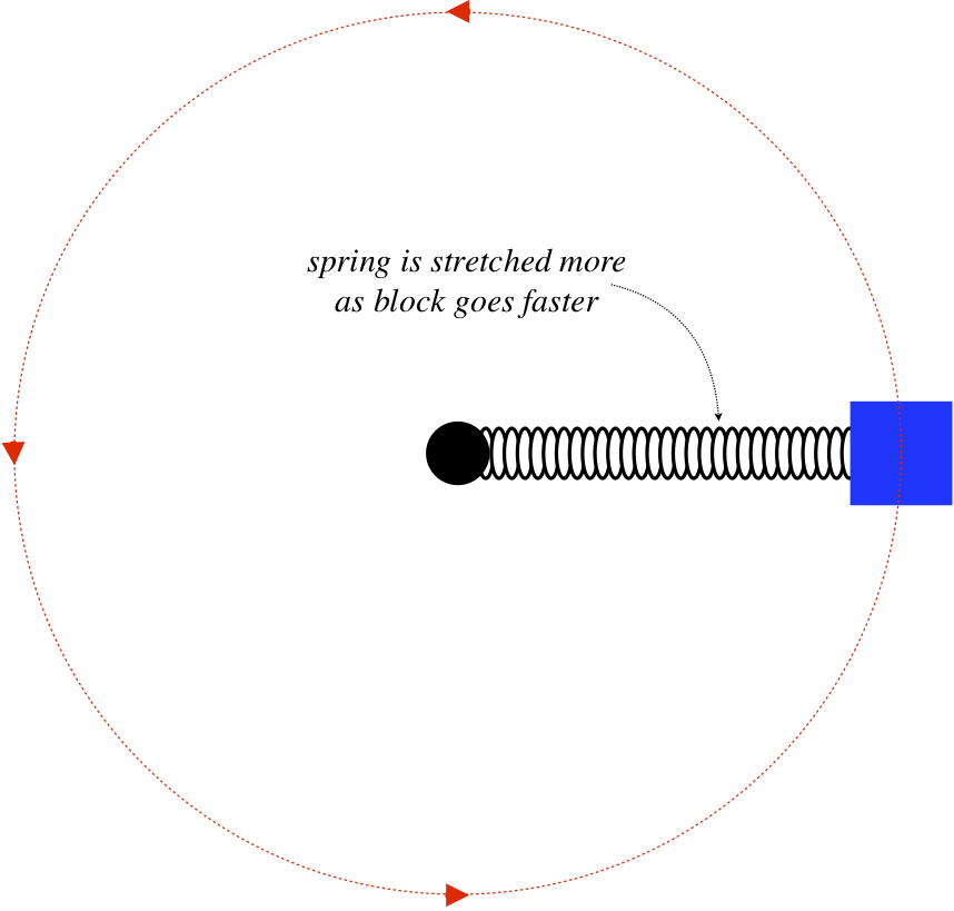
A block is attached to one end of a massless spring, the other end of which is attached to a vertical fixed peg in a frictionless horizontal surface. The block is spun around a circle, and the spring stretches as a result of this motion. In fact, the faster the motion, the more the spring stretches. To stretch any spring, both ends need to be pulled simultaneously. Clearly the peg is pulling on one end of the spring as the block goes in the circle, but what force is pulled the block outward to stretch the spring?
- Solution
-
The block is not pulled outward! It is only pulled inward (by the spring). It is not the block that needs to be pulled outward to stretch the spring, but rather the spring that needs to be pulled that way. The spring pulls the block inward (keeping it accelerating centripetally), and the third-law-pair force of the block on the spring is what pulls the spring outward.
This points out possibly better than any other example the importance of isolating objects with force diagrams. The block here is not a conduit for some mysterious force pulling out on the spring – it is the object pulling out on the spring. You thoroughly need to trust the third law here to get the force between the spring and the block, and you need to thoroughly trust the second law to realize that the block does not require another force on it outward to balance the spring force, because it is accelerating.
Now for the promised example that incorporates motion following the step-by-step prescription given earlier. What makes this problem interesting is the information that is hidden within the wording...
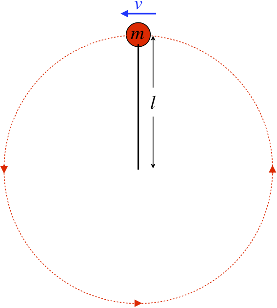
A rock on a string flies around in a circle in a vertical plane (in the presence of the earth's gravity) such that it just barely gets by the top (the string remains stretched to its full length, but there is no tension) as it continues in its circular path. Find the speed of the rock in terms of the length of the string.
- draw a diagram
- isolate the relevant objects and draw free-body diagrams for them
- choose coordinate systems for the diagrams that are convenient
We'll choose down as the positive \(y\)-direction.
- break forces into components in the coordinate system chosen
Unnecessary here.
- sum the forces in the \(x\) and \(y\) directions and apply Newton's second law in both directions
\[a = \dfrac{\sum {F_y} }{m} = \dfrac{T + mg}{m}\]
- apply the constraints
The first constraint is that the rock barely makes it around. What does this mean? To answer this, think about what would happen if the rock was moving any slower... It would fall out of the circle, which means the string would not remain straight. This would mean that the tension is zero. So the condition of "just making it around" is equivalent to requiring that the tension vanishes. The second constraint is that the rock is traveling in a circle, which requires that the acceleration is centripetal, with the radius of the circle equalling the length of the string (note there is no horizontal force at the top, so there is no tangential component to the acceleration). Stating both mathematically:
\[T=0,\;\;\;\;\; a=\dfrac{v^2}{l} \]
- do the algebra
Simple enough:
\[v=\sqrt{gl} \]
While this is a pretty simple example in terms of the steps taken, it points out one very important aspect of these problems. If you don’t spend some time thinking about what is physically happening, you are likely to overlook the “hidden” information in the wording of the problem. This isn’t intended as a trick to trip you up – this is exactly what you run into in the real world when you need to solve a real problem. You need to be able to convert descriptive aspects of a system into mathematically-analyzable quantities.
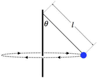
Example \(\PageIndex{4}\)
A tetherball swings around a pole, making a full circle once every 1.5s. The total length of the rope is 2.4m. Calculate the angle θ that the rope makes with the pole. The rope has negligible mass.
- Solution
-
Start with a force diagram of the ball, including a coordinate system:
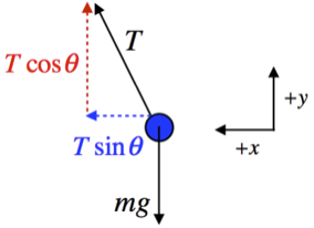
Next sum the forces along the \(x\) and \(y\) axes and apply Newton's second law:
\[ \begin{array}{l} a_x = \dfrac{T \sin \theta}{m} \\ a_y = \dfrac{T \cos \theta - mg}{m} \end{array} \nonumber \]
The acceleration in the \(x\)-direction is centripetal, with the radius of its circular motion equal to the horizontal leg of the right triangle whose hypotenuse is the length of the string. The speed is constant, so it equals the circumference of the circle divided by the time for the trip. Putting all this together gives:
\[ \left. \begin{array}{l} a_x = \dfrac{v^2}{R} \\ R = l \sin \theta \\ v = \dfrac{2 \pi R}{t} \end{array} \right\} \;\;\; \Rightarrow \;\;\; a_x = \dfrac{4 \pi^2 l \sin \theta}{t^2} \nonumber \]
The acceleration in the \(y\)-direction is zero, so plugging the accelerations into the equations from Newton's second law and eliminating \( \frac{T}{m} \) from the two equations gives:
\[ \left. \begin{array}{l} a_x = \dfrac{4 \pi^2 l \sin \theta}{t^2} = \dfrac{T \sin \theta}{m} \;\;\; \Rightarrow \;\;\; \dfrac{T}{m} = \dfrac{4 \pi^2 l }{t^2} \\ a_y = 0 = \dfrac{T \cos \theta - mg}{m} \;\;\; \Rightarrow \;\;\; \dfrac{T}{m} = \dfrac{g}{\cos \theta} \end{array} \right\} \;\;\; \Rightarrow \;\;\; \theta = \cos ^{-1} \left(\dfrac{g t^2}{4 \pi^2 l} \right) = \boxed{76.5^o} \nonumber \]