
11.5: A Terminated Line


- Last updated
- Jun 21, 2021
- Save as PDF

( \newcommand{\kernel}{\mathrm{null}\,}\)
Any discontinuity in the properties of a transmission line results in a reflected pulse and a transmitted pulse whose amplitudes are smaller than the original pulse amplitude. In order to see how this comes about, consider a few simple cases
(i) Two pulses of identical shape, but mirror images, propagate towards one another on an infinite line, Figure (11.5.8(a)). The experiment is set up so that the pulses collide at z=0. Maxwell’s equations are linear, and we assume that the dielectric and magnetic response of the material of which the line is made is also linear. For linear response, the total potential difference at any point is just the sum of the potential differences associated with the two pulses; similarly, the current at any point on the line is the sum of the currents in the individual pulses. In particular, at z=0 where the two pulses collide the current is zero! The pulses pass through each other without interacting. During the overlap time, the voltage at z=0 will be twice as large as it would be for a single pulse. The system of two pulses shown in Figure (11.5.8) satisfies the boundary conditions at z=0 for an open line, i.e. I=0. It can be deduced from this that an observer placed to the left of the point z=0 could not tell the difference between an experiment in which a single pulse is injected into a line that is open (i.e. terminated by an open circuit) at z=0 or an experiment in which two mirror image pulses are injected into an infinite line from opposite directions.
Another way of obtaining this result starts from the general expressions for the voltage and current on a transmission line,
V(z,t)=F(z−vt)+G(z+vt),
and
I(z,t)=F(z−vt)/Z0−G(z+vt)/Z0.
The current must be zero for all times at an open circuit, i.e. at that point on the line
I=0=(F−G)/Z0.
It follows from this that at the open circuit F=G for all times, and therefore the reflected pulse at any time, G(z+vt), must be the mirror image of the incident pulse F(z-vt) where the mirror is located at the position of the open circuit.
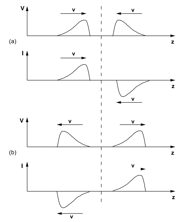
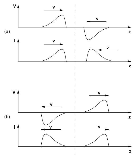
(ii) Two pulses of identical shape, but one pulse is a mirror image of the other and is inverted as shown in Figure (11.5.9), are launched towards one another on an infinite line. They collide at z=0. Because the system is a linear one the pulses simply pass through one another without interacting in any way. In this case the potential difference at z=0 always remains equal to zero because the two voltage pulses cancel one another. On the other hand, the two current pulses add, so that at z=0 the current becomes twice as large as it would be for the passage of a single pulse. Thus these two counter propagating pulses satisfy the boundary conditions at z=0 required for a short circuit, i.e. at z=0 one has R=V/I=0. We can deduce from this thought experiment that a pulse is inverted upon reflection from the end of a shorted line.
The principle illustrated by these two examples can be extended to cover the case of a line terminated by an arbitrary resistance R Ohms. Let the incident pulse have an amplitude V0 Volts. Let the amplitude of the reflected pulse be VR Volts. The corresponding currents are I0 = V0/Z0 and IR = −VR/Z0; the latter current is negative because the pulse is propagating from right to left. Suppose that the pulses collide at z=0. At z=0 one has, by superposition,
V=V0+VR
and
I=I0+IR=V0Z0−VRZ0.
But we require R=V/I at the point z=0. Therefore
R=Z0(V0+VRV0−VR).
This equation can be solved in order to find the amplitude of the reflected pulse and the reflection coefficient, ρ = VR/V0:
ρ=(VRV0)=((R/Z0)−1)((R/Z0)+1).
The two cases explicitly treated above are contained in Equation (???) as limiting cases: if R → ∞ then ρ → +1, and the voltage pulse is reflected without a change in amplitude and with no change in sign; if R → 0 then ρ → −1, and the voltage pulse is reflected without a change in amplitude but the pulse is inverted. On the other hand, if R = Z0 there is no reflected pulse because ρ = 0: the pulse is completely absorbed by the terminating resistance. A line terminated by a resistance equal to the characteristic impedance of the line looks like an infinite line to the generator.
This method for dealing with a discontinuity on the line can be extended to treat a capacitive or an inductive termination. At a capacitor one requires
Q=CV
or
I=dQdt=CdVdt.
But I = I0 + IR and V = V0 + VR, so that
I0+IR=V0Z0−VRZ0=C(dV0dt+dVRdt).
This relation gives a differential equation from which VR(t) can be calculated from the known time dependence of the initial pulse V0(t):
dVRdt+(1CZ0)VR=−dV0dt+(1CZ0)V0(t).
As an example, consider an incident rectangular pulse whose time dependence is shown in Figure (11.5.10). The derivative of a rectangular pulse consists of two very sharp impulses; one impulse is associated with the leading edge at t=0 where dV/dt = V0δ(t), and the other impulse is associated with the trailing edge at t=T seconds where dV/dt = −V0δ(t − T). In the time interval from t=0 to t=T the reflected pulse amplitude at the termination is given by (from Equation (???))
VR(t)=V0−2V0exp(−t/τ),
where τ = CZ0. At t=0 the reflected voltage pulse has the amplitude VR = −V0: this makes sense because the initially uncharged capacitor looks like a short circuit. The capacitor charges at a rate determined by the time constant τ = CZ0 until the voltage across it reaches the value 2V0: it then looks like an open circuit because it can accept no more charge. When the capacitor is fully charged and becomes equivalent to an open circuit the reflected pulse amplitude becomes equal to the incident pulse amplitude and the potential drop across the capacitor is V = V0 + VR = 2V0. (It has been assumed that
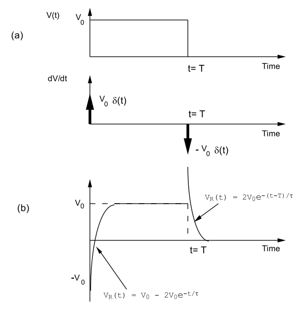
the width of the pulse, T, is much longer than the time constant τ = CZ0). At the end of the incident pulse, t=T, the capacitor, charged to a potential difference of 2V0 Volts, just discharges into the line with a time constant τ = CZ0, and therefore
VR(t)=2V0exp(−[t−T]/τ)
for t ≥ T.
Similar arguments can be used to discuss a line terminated by an inductor whose resistance is much smaller than the characteristic impedance, Z0. The potential drop across an inductor is related to the current passing through it by the relation
V=L(dIdt).
But at z=0 on the cable where the pulses overlap
I=I0+IR=V0Z0−VRZ0,
and
V=V0+VR,
where V0(t) is the amplitude of the incident pulse and VR(t) is the corresponding amplitude of the reflected pulse. From the boundary condition Equation (???) one obtains
V0(t)+VR(t)=LZ0(dV0dt−dVRdt),
or
dVRdt+VRτ=(dV0dt)−V0/τ,
where τ = L/Z0. The time variation of the incident pulse at z=0 is known so that the differential Equation (???) can be solved for the time variation of the reflected pulse using the condition that VR(t) is identically zero for times before the incident pulse arrives at the termination. Consider, as an example, the rectangular pulse of duration T, shown in Figure (11.5.11), where the length of the pulse T is much longer than the time constant τ = L/Z0. The derivative of the incident pulse is zero everywhere except at t=0 where dV0/dt = V0δ(t), and at t=T where dV0/dt = −V0δ(t − T). These impulses produce steps in
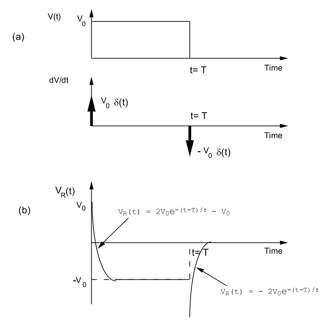
the reflected voltage, VR, of +V0 at t=0 and of −V0 at t=T. The reflected pulse amplitude at t=0 is +V0 because initially the inductor looks like an open circuit since there is no current flow. Eventually the current through the inductor builds up to a steady state value and the voltage drop across the inductor becomes zero; at this point the inductor looks like a short circuit so that the reflected voltage pulse amplitude is VR = −V0. The time variation of the reflected voltage pulse is
VR(t)=2V0exp(−t/τ)−V0,
for 0 < t ≤ T. Immediately after t=T seconds the driving pulse has become zero, and so the energy stored in the inductor decays into the transmission line at a rate determined by the inductance and the characteristic impedance, Z0:
VR(t)=−2V0exp(−[t−T]/τ),
for t ≥ T. The reflected pulse has a negative voltage because because the collapse of the magnetic field in the inductor coil operates to maintain a positive current flow. In a reflected pulse a positive current flow is associated with a negative voltage.
The above methods can be extended to treat a transmission line terminated by an arbitrary impedance.