
20.1: Batteries and Simple Circuits


- Last updated
- Mar 28, 2024
- Save as PDF
( \newcommand{\kernel}{\mathrm{null}\,}\)
A battery is an electric component that provides a constant electric potential difference (a fixed voltage) across its terminals. Luigi Galvani was the first to realize that certain combination of metals placed into contact with each other can lead to an electric potential difference (or rather, they can make the legs of a dead frog twitch, which we now understand to be from the potential difference due to the metals). Effectively, Galvani created the first “electrochemical cell”. Alessandro Volta then combined several of these cells together to form the “voltaic pile”, which is what we would now call a battery (a battery, technically, is a combination of several cells, a battery of cells, although one often uses the term battery even if only a single electric cell is involved).
The Electrochemical Cell
An electric cell can be constructed from metals that have different affinities to be dissolved in acid. A simple cell, similar to that originally made by Volta, can be made using zinc and carbon as the “electrodes” (Volta used silver instead of carbon) and a solution of dilute sulfuric acid (the liquid is called the “electrolyte”), as illustrated in Figure \PageIndex{1}. Before the cell is constructed, the electrodes and the electrolyte are all electrically neutral.

Once the zinc is immersed in the electrolyte, the zinc atoms tend to dissolve into the electrolyte in the form of zinc ions (doubly charged, Zn^{2+}). This leaves an excess of electrons on the zinc electrode, resulting in a net negative electric charge. Similarly, the positively charged zinc ions attract electrons from the carbon electrode into the solution, leaving the carbon electrode positively charged. Very quickly, an equilibrium is reached, since at some point, the negative charge of the zinc electrode will electrically attract positive zinc ions, preventing any more zinc ions from dissolving into the solution. Similarly, as the carbon electrode builds a positive charge, that charge will eventually prevent electrons from “jumping” into the solution. At this point, there will be a fixed electric potential difference between the two electrodes (terminals) of the battery.
If the two electrodes are connected together through a resistor, the electrons will leave the zinc electrode, cross the resistor, and end up on the positive carbon electrode. This will leave space for more electrons on the zinc electrode, so more zinc ions will dissolve into the solution. Thus, a circuit is formed, where electron travel up the zinc electrode, through the resistor and back down the carbon electrode. At the same time, more and more zinc ions dissolve into the electrolyte, until the zinc electrode is completely dissolved. In practice, the zinc ions travel through the solution and plate onto the carbon electrode (the electrons do not quite “jump” into the electrolyte, rather, it is the zinc ions that move in the electrolyte). Since the charge on the electrodes is continuously replenished, the potential difference between the electrodes remains constant even as current is flowing.
The electric cell will stop working once the zinc electrode has completely dissolved (this is what happens when your battery is dead). Note that there is also a maximum current that the cell can supply, which depends on the rate at which the zinc can dissolve into the electrolyte and plate onto the carbon electrode. If the electrodes of the cell are connected with a very low resistance resistor, the resulting current will be too large for the potential difference to be maintained. Most electric cells work in similar ways, although the chemical reactions can be much more complex. Sometimes, the chemical reaction is reversible; one could use a different battery to apply a negative voltage to the carbon electrode to reverse the reaction and plate the zinc back onto the zinc electrode, thus “recharging the battery” (and converting electric energy back into stored chemical potential energy).
The ideal battery in a circuit
As we proceed, we will use the term “battery” loosely to refer to a device (such as an electric cell or collection of cells) that can provide a fixed potential difference between two terminals (or electrodes). Figure \PageIndex{2} shows the circuit diagram for a battery, consisting in two (or four) vertical bars, with the larger bar indicating the positive terminal of the battery.
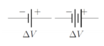
Figure \PageIndex{3} shows the circuit diagram symbols that are used for a resistor (different symbols are used in North American and in Europe).
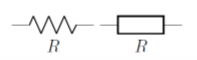
Figure \PageIndex{4} shows a circuit diagram for a very simple circuit consisting of a single 9\text{V} battery connected to a 2\Omega resistor. When drawing a circuit diagram (or making a real circuit), one connects the various components together (e.g. batteries and resistors) with segments of wire that have zero resistance, even if, in practice, wires always have some resistance. However, since the wires are connected in series with resistors (or other components that have a resistance), one can always include the resistance of the wires by adding it to the resistance of the other components. For example, in Figure \PageIndex{4}, if the wires have a total resistance of 1\Omega, we could simply model the circuit as if the resistor had a resistance of 3\Omega instead of 2\Omega. In practice, this is usually accounted for when a circuit diagram is made (i.e. any resistors include the resistance of the wires connected to it).
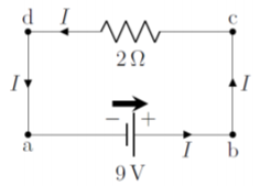
The circuit in Figure \PageIndex{4} is simple to analyze. In this case, whichever charges exit one terminal of the battery, must pass through the resistor and then enter the other terminal of the battery. We always use conventional current to analyze a circuit. Thus, we model the circuit as if positive charges exit the positive terminal of the battery, go through the resistor, and then enter the negative terminal of the battery.
We recommend that you always draw a “battery arrow” for each battery in a circuit diagram to indicate the direction in which the electric potential increases and in which direction the conventional current would exit the battery if a simple resistor were connected across the battery. In complex circuits, the current may not necessarily flow in the same direction as the battery arrow, and the battery arrow makes it easier to analyze those circuits. We also indicate the current that is flowing in any wire of the circuit by drawing an arrow in the direction of current on that wire (labeled I in Figure \PageIndex{4}).
It is helpful to think of the value of the electric potential along different parts of a circuit, as illustrated in Figure \PageIndex{5} for the same circuit as in Figure \PageIndex{4}.
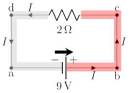
Since the wires have no resistance, the electric potential is constant along a wire. In other words, because the wire has no resistance, the charges/current cannot dissipate any power in the wire (P=I^2R), and the charges do not “loose” any potential energy (and the potential thus cannot change). The only place where the charges can dissipate energy is inside the resistor. Once the charges have crossed the resistor, the electric potential in the wire is again constant until they reach the other terminal of the battery. Thus, in this simple circuit, the electric potential difference across the resistor is the same as the potential difference across the terminals of the battery. This is shown by the colored areas in Figure \PageIndex{5}. If we choose 0\text{V} to be defined at the negative terminal of the battery, then the potential is 9\text{V} everywhere in the red area (to the right of the resistor), and 0\text{V} everywhere in the grey area (to the left of the resistor).
We can apply Ohm’s Law (the macroscopic version) to the resistor and determine the current in the circuit, since we know the potential difference across the resistor:
\begin{aligned} \Delta V&=RI\\[4pt] \therefore I&=\frac{\Delta V}{R}=\frac{(9\text{V})}{(2\Omega)}=4.5\text{A}\end{aligned}
It is helpful to think of circuits in terms of energy. Charges move along the circuit and their potential energy changes as they go through components, while it remains constant as they move through a wire. If a positive charges enters the negative terminal of a battery and exits the positive terminal, its potential energy will have increased. If that charge then enters a resistor, its potential energy will decrease as it moves through the resistor, since the charge will “use” its potential energy to heat up the resistor. Batteries provide the energy to “push” the charges through the resistors in the circuit by converting chemical potential energy into the electrical potential energy of the charges.
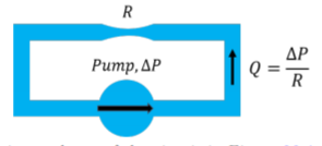
It is also useful to make the analogy with fluid dynamics; one can think of the battery as a pump that is continuously pushing a viscous incompressible fluid through a pipe with a narrow section, as illustrated in Figure \PageIndex{6}. The wide section of the pipe is akin to the wires with no resistance, and the narrow section is akin to the resistor. The pressure difference generated by the pump is analogous to the voltage produced by the battery, and the flow rate of the liquid is analogous to the electric current. The pressure in the pipe does not drop in the wide section, if there is no resistance. The entire pressure drop of the fluid is across the narrow section, just as the voltage only drops across the resistor.
Two resistors, of 2\Omega and 4\Omega, respectively, are connected in series to a 12\text{V} battery. What is the current through each of the resistors, and what is the voltage across each resistor?
Solution
We start by making a circuit diagram, as in Figure \PageIndex{7}, showing the resistors, the current, I, the battery and the battery arrow. Note that since this is a closed circuit with only one path, the current through the battery, I, is the same as the current through the two resistors.
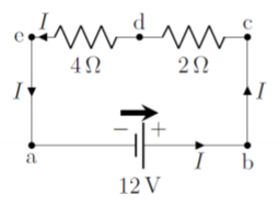
If we choose the potential on the negative side of the battery to be 0\text{V}, then points a and e on the diagram are at a potential of 0\text{V}, since potential cannot change in a wire with no resistance. Similarly, the points at b and c are at a potential of 12\text{V} (relative to points a and e). At point d, between the two resistors, the potential will be between 0\text{V} and 12\text{V}, since the potential will “drop” as the current goes through the 2\Omega resistor.
The easiest way to determine the current through this simple circuit is to combine the two resistors into a single effective resistor with resistance:
\begin{aligned} R_{eff}=(2\Omega)+(4\Omega)=6\Omega\end{aligned}
so that the circuit can be simplified to that shown in Figure \PageIndex{8}:
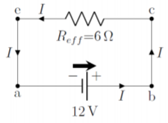
The potential difference across the effective resistor is the same as that across the battery (between points e and c), so that Ohm’s Law can be applied to the effective resistor to determine the current that traverses it:
\begin{aligned} \Delta V &= R_{eff}I\\[4pt] \therefore I&=\frac{\Delta V}{R_{eff}}=\frac{(12\text{V})}{(6\Omega)}=2\text{A}\end{aligned}
This current is the same that traverses each individual resistor, since it is the same as the current that goes through the battery. Referring back to the full circuit (Figure \PageIndex{7}), we can now use Ohm’s Law to calculate the voltage drop across each resistor, since we know the current through each resistor. The voltage across the 2\Omega resistor is given by:
\begin{aligned} \Delta V_{2\Omega}=RI=(2\Omega)(2\text{A})=4\text{V}\end{aligned}
and the voltage across the 4\Omega resistor is given by:
\begin{aligned} \Delta V_{4\Omega}=RI=(4\Omega)(2\text{A})=8\text{V}\end{aligned}
Note that the sum of these two voltages is equal to the voltage increase across the battery, by conservation of energy. Consider the electric potential at different points in Figure \PageIndex{7} as you move clockwise around the loop starting at point a. If the electric potential is defined to be 0\text{V} at the negative end of the battery (points a and e), the potential at point d (between the resistors) is the potential at point e plus the potential difference across the 4\Omega resistor:
\begin{aligned} V_d = V_e+\Delta V_{4\Omega}=(0\text{V})+(\Delta V_{4\Omega})=8\text{V}\end{aligned}
If we then add the potential difference across the 2\Omega resistor to the potential at point d, we find that the potential at point c is V_c=V_d+\Delta V_{2\Omega}=12\text{V}, as expected, since this corresponds to the potential at the positive terminal of the battery.
Discussion
In this example, we showed how one can model a circuit by combining resistors together into effective resistors to simplify the circuit. We also showed how the potential differences across different components in a circuit must add up to zero (the voltage drops across the resistors must sum to the voltage increase across the battery).
What is the voltage across the combination of a 3\text{ V} battery connected in series with a 6\text{ V} battery, where the negative terminal of the 6\text{ V} battery faces the positive terminal of the 3\text{ V} battery?
- 9\text{ V}.
- 6\text{ V}.
- 3\text{ V}.
- 0\text{ V}.
- Answer
The real battery in a circuit
So far, we have modeled batteries as “ideal” devices that provide a fixed potential difference. In reality, this neglects the fact that the materials that make the battery will themselves have a resistance. For example, if electrons want to leave the zinc rod in the electric cell illustrated in Figure \PageIndex{1}, they will loose some energy as they pass through the zinc. Thus, when modeling a real battery in a circuit, it is important to include its “internal resistance”, as a resistor in series with the potential difference. This is illustrated in Figure \PageIndex{9}, which shows the two terminals of a real battery, an ideal battery (with a fixed potential difference, \Delta V_{ideal}), and its internal resistance, r (which can be drawn on either side of the battery).
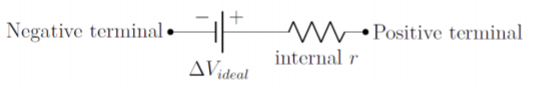
It is important to note that the potential difference across the terminals of the real battery is only equal to the potential difference across the ideal battery if there is no current flowing through the battery. If there is a current, I, flowing through the internal resistance, the electric potential will decrease by an amount Ir across the internal resistance, and the voltage across the real terminals will be \Delta V_{ideal}-Ir.
When no resistance is connected across a real battery, the potential difference across its terminals is measured to be 6\text{V}. When a R=2\Omega resistor is connected across the battery, a current of 2\text{A} is measured through the resistor. What is the internal resistance, r, of the battery, and what is the voltage across its terminals when the R=2\Omega resistor is connected?
Solution
The real battery can be modeled as an ideal battery with potential difference, \Delta V_{ideal}, in series with an internal resistance, r. While we do not know the value of the internal resistance, we are told that the potential difference across the terminals of the real battery is 6\text{V} when no current flows through it. Since no current flows through the internal resistance, the voltage does not drop across the internal resistance, and the voltage across the terminals of the real battery (e.g. Figure \PageIndex{9}) must thus be equal to the voltage across the terminals of the ideal battery, so that \Delta V_{ideal}=6\text{V}.
With this information, we can make a circuit diagram for the case when the 2\Omega resistor is connected across the terminals of the real battery, as in Figure \PageIndex{10}.
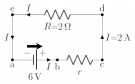
The terminals of the real battery are located at points a and c of the diagram, whereas the terminals of the ideal battery corresponds to points a and b. When no current flows through the internal resistor, r, there is no voltage drop across that resistor and the potential at b will be equal to the potential at c, as we argued above.
The circuit in Figure \PageIndex{10} is now identical to that analyzed in Example 20.1.1, and can be treated the same way. We can combine the 2\Omega resistor with the internal resistance, r, in series to obtain an effective resistor, R_{eff}=r+R. The voltage drop across the effective resistor will be the same as the potential difference across the ideal battery, and we can make use of Ohm’s Law to find the internal resistance, r:
\begin{aligned} \Delta V_{ideal}&= R_{eff}I=(r+R)I\\[4pt] \therefore r &= \frac{\Delta V_{ideal}}{I}-R=\frac{(6\text{V})}{(2\text{A})}-(2\Omega)=1\Omega\end{aligned}
Now that we know the internal resistance, we can determine the voltage drop across the internal resistor, using Ohm’s Law:
\begin{aligned} \Delta V_r = rI=(1\Omega)(2\text{A})=2\text{V}\end{aligned}
The voltage drop across the real terminals of the battery (between points a and c), is thus given by:
\begin{aligned} \Delta V_{real}=\Delta V_{ideal}-\Delta V_r=(6\text{V})-(2\text{V})=4\text{V}\end{aligned}
Again, you can verify that the voltage drops across the two resistors will sum to the total voltage drop across the terminals of the ideal battery.
Discussion
Modeling real batteries is not so different from modeling ideal batteries, since one only needs to include an internal resistance into the circuit. The key difference with a real battery is that the voltage across its real terminals depends on what is connected to the battery. In the example above, the battery has a voltage of 6\text{V} across its (real) terminals when nothing is connected, but the voltage drops to 4\text{V} when a 2\Omega resistor is connected.
Suppose that you would like to measure the ideal voltage of a real battery by connecting a measurement device (a voltmeter) across its terminals. In order to get the most accurate reading, should you choose a voltmeter with a high resistance, or a voltmeter with a low resistance?
- High resistance.
- Low resistance.
- It doesn’t matter if the voltmeter has a high or low resistance.
- Answer