
11.6: Lenses and Geometrical Optics
- Page ID
- 45002
\( \newcommand{\vecs}[1]{\overset { \scriptstyle \rightharpoonup} {\mathbf{#1}} } \)
\( \newcommand{\vecd}[1]{\overset{-\!-\!\rightharpoonup}{\vphantom{a}\smash {#1}}} \)
\( \newcommand{\dsum}{\displaystyle\sum\limits} \)
\( \newcommand{\dint}{\displaystyle\int\limits} \)
\( \newcommand{\dlim}{\displaystyle\lim\limits} \)
\( \newcommand{\id}{\mathrm{id}}\) \( \newcommand{\Span}{\mathrm{span}}\)
( \newcommand{\kernel}{\mathrm{null}\,}\) \( \newcommand{\range}{\mathrm{range}\,}\)
\( \newcommand{\RealPart}{\mathrm{Re}}\) \( \newcommand{\ImaginaryPart}{\mathrm{Im}}\)
\( \newcommand{\Argument}{\mathrm{Arg}}\) \( \newcommand{\norm}[1]{\| #1 \|}\)
\( \newcommand{\inner}[2]{\langle #1, #2 \rangle}\)
\( \newcommand{\Span}{\mathrm{span}}\)
\( \newcommand{\id}{\mathrm{id}}\)
\( \newcommand{\Span}{\mathrm{span}}\)
\( \newcommand{\kernel}{\mathrm{null}\,}\)
\( \newcommand{\range}{\mathrm{range}\,}\)
\( \newcommand{\RealPart}{\mathrm{Re}}\)
\( \newcommand{\ImaginaryPart}{\mathrm{Im}}\)
\( \newcommand{\Argument}{\mathrm{Arg}}\)
\( \newcommand{\norm}[1]{\| #1 \|}\)
\( \newcommand{\inner}[2]{\langle #1, #2 \rangle}\)
\( \newcommand{\Span}{\mathrm{span}}\) \( \newcommand{\AA}{\unicode[.8,0]{x212B}}\)
\( \newcommand{\vectorA}[1]{\vec{#1}} % arrow\)
\( \newcommand{\vectorAt}[1]{\vec{\text{#1}}} % arrow\)
\( \newcommand{\vectorB}[1]{\overset { \scriptstyle \rightharpoonup} {\mathbf{#1}} } \)
\( \newcommand{\vectorC}[1]{\textbf{#1}} \)
\( \newcommand{\vectorD}[1]{\overrightarrow{#1}} \)
\( \newcommand{\vectorDt}[1]{\overrightarrow{\text{#1}}} \)
\( \newcommand{\vectE}[1]{\overset{-\!-\!\rightharpoonup}{\vphantom{a}\smash{\mathbf {#1}}}} \)
\( \newcommand{\vecs}[1]{\overset { \scriptstyle \rightharpoonup} {\mathbf{#1}} } \)
\( \newcommand{\vecd}[1]{\overset{-\!-\!\rightharpoonup}{\vphantom{a}\smash {#1}}} \)
\(\newcommand{\avec}{\mathbf a}\) \(\newcommand{\bvec}{\mathbf b}\) \(\newcommand{\cvec}{\mathbf c}\) \(\newcommand{\dvec}{\mathbf d}\) \(\newcommand{\dtil}{\widetilde{\mathbf d}}\) \(\newcommand{\evec}{\mathbf e}\) \(\newcommand{\fvec}{\mathbf f}\) \(\newcommand{\nvec}{\mathbf n}\) \(\newcommand{\pvec}{\mathbf p}\) \(\newcommand{\qvec}{\mathbf q}\) \(\newcommand{\svec}{\mathbf s}\) \(\newcommand{\tvec}{\mathbf t}\) \(\newcommand{\uvec}{\mathbf u}\) \(\newcommand{\vvec}{\mathbf v}\) \(\newcommand{\wvec}{\mathbf w}\) \(\newcommand{\xvec}{\mathbf x}\) \(\newcommand{\yvec}{\mathbf y}\) \(\newcommand{\zvec}{\mathbf z}\) \(\newcommand{\rvec}{\mathbf r}\) \(\newcommand{\mvec}{\mathbf m}\) \(\newcommand{\zerovec}{\mathbf 0}\) \(\newcommand{\onevec}{\mathbf 1}\) \(\newcommand{\real}{\mathbb R}\) \(\newcommand{\twovec}[2]{\left[\begin{array}{r}#1 \\ #2 \end{array}\right]}\) \(\newcommand{\ctwovec}[2]{\left[\begin{array}{c}#1 \\ #2 \end{array}\right]}\) \(\newcommand{\threevec}[3]{\left[\begin{array}{r}#1 \\ #2 \\ #3 \end{array}\right]}\) \(\newcommand{\cthreevec}[3]{\left[\begin{array}{c}#1 \\ #2 \\ #3 \end{array}\right]}\) \(\newcommand{\fourvec}[4]{\left[\begin{array}{r}#1 \\ #2 \\ #3 \\ #4 \end{array}\right]}\) \(\newcommand{\cfourvec}[4]{\left[\begin{array}{c}#1 \\ #2 \\ #3 \\ #4 \end{array}\right]}\) \(\newcommand{\fivevec}[5]{\left[\begin{array}{r}#1 \\ #2 \\ #3 \\ #4 \\ #5 \\ \end{array}\right]}\) \(\newcommand{\cfivevec}[5]{\left[\begin{array}{c}#1 \\ #2 \\ #3 \\ #4 \\ #5 \\ \end{array}\right]}\) \(\newcommand{\mattwo}[4]{\left[\begin{array}{rr}#1 \amp #2 \\ #3 \amp #4 \\ \end{array}\right]}\) \(\newcommand{\laspan}[1]{\text{Span}\{#1\}}\) \(\newcommand{\bcal}{\cal B}\) \(\newcommand{\ccal}{\cal C}\) \(\newcommand{\scal}{\cal S}\) \(\newcommand{\wcal}{\cal W}\) \(\newcommand{\ecal}{\cal E}\) \(\newcommand{\coords}[2]{\left\{#1\right\}_{#2}}\) \(\newcommand{\gray}[1]{\color{gray}{#1}}\) \(\newcommand{\lgray}[1]{\color{lightgray}{#1}}\) \(\newcommand{\rank}{\operatorname{rank}}\) \(\newcommand{\row}{\text{Row}}\) \(\newcommand{\col}{\text{Col}}\) \(\renewcommand{\row}{\text{Row}}\) \(\newcommand{\nul}{\text{Nul}}\) \(\newcommand{\var}{\text{Var}}\) \(\newcommand{\corr}{\text{corr}}\) \(\newcommand{\len}[1]{\left|#1\right|}\) \(\newcommand{\bbar}{\overline{\bvec}}\) \(\newcommand{\bhat}{\widehat{\bvec}}\) \(\newcommand{\bperp}{\bvec^\perp}\) \(\newcommand{\xhat}{\widehat{\xvec}}\) \(\newcommand{\vhat}{\widehat{\vvec}}\) \(\newcommand{\uhat}{\widehat{\uvec}}\) \(\newcommand{\what}{\widehat{\wvec}}\) \(\newcommand{\Sighat}{\widehat{\Sigma}}\) \(\newcommand{\lt}{<}\) \(\newcommand{\gt}{>}\) \(\newcommand{\amp}{&}\) \(\definecolor{fillinmathshade}{gray}{0.9}\)Geometrical Optics
The idea of geometrical optics is to understand the effects of refraction and reflection on beams of light, ignoring the effects of diffraction. This is really only Snell’s law and geometry. One application of these ideas will be in the discussion of the rainbow in the next section. There we use what is called “ray tracing” which as the name suggests is simply keeping track of what each ray of light does as it passes through the drop. A spherical drop is a “thick lens.” Obviously, there is no sense in which a sphere could be regarded as “thin.” In this section we are going to see how to give a simpler approximate description of what a “thin lens” does. In fact, if we were designing a very precise optical instrument, we would still use ray tracing to get the fine details right. But the thin lens analysis is a good approximate starting point and will help us understand what is happening in some important situations.
Technically, what “thin” means in this context is that if a narrow beam of light approximately perpendicular to the plane of the lens comes into the lens at some point on one side, it comes out at about the same point on the other side. If we ignore the small change in position, this simplifies the analysis and gives us the thin lens formula.
Thin Spherical Lenses
In Chapter 11, we derive the formula for the angular change in a narrow (we are ignoring diffraction) beam of light due to a prism. The analysis is uses the geometrical construction
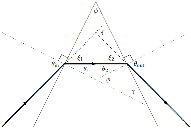
Figure \( 11.26\):
shown in Figure \( 11.26\) and gives \[\begin{gathered}
\delta=\theta_{\text {in }}+\theta_{\text {out }}-\theta_{1}-\theta_{2} \\
\approx n\left(\theta_{1}+\theta_{2}\right)-\phi \approx(n-1) \phi
\end{gathered}\]
where the first is exact and the second follows in the limit in which the \(\theta\) angles are small. In this limit, the angular deflection is independent of the incoming angle.
lenses and small angles
We can use this result to understand how a lens focuses light. A lens is a device in which the angular change given to the beam is proportional to the distance from the axis for small angles and distances — \[\delta \approx h / f\]
where \(f\) is length. This is approximately true for a piece of glass with surfaces that are parts of spheres. In Figure \( 11.27\) is a diagram showing how this works for a lens which is flat on one side and a partial sphere with radius \(r_{1}\) on the other. In the diagram, |(\theta_{1}\) is the angle of the “effective prism” seen by the part of a beam at distance \(h\) from the axis. It should be clear from the figure that if \(\theta_{1}\) is small, it is proportional to \(h\). \[\theta_{1} \approx \sin \theta_{1}=\frac{h}{r_{1}}\]
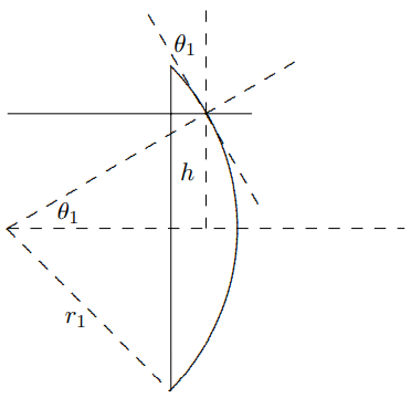
Figure \( 11.27\):
More often, the lens is curved on both sides. If the radii are \(r_{1}\) and \(r_{2}\), the result looks like Figure \( 11.28\). Figure \( 11.28\) shows the beam at the very tip of the lens for convenience, but as
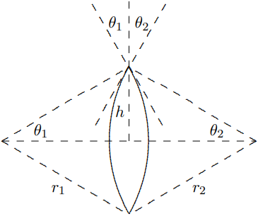
Figure \( 11.28\):
the previous diagram should make clear, \(\theta_{1}+\theta_{2}\) is the “effective prism” angle for any \(h\). The figure also exaggerates the curvature of the two sides, so that the lens pictured is not really “thin.” A thin lens looks more like Figure \( 11.29\). This is important because if the lens is fat, the height \(h\) is not very well-defined because if the light inside the lens is not horizontal, we might have one \(h\) where the light enters the lens and a very different \(h\) where it come out. But if the lens is thin and if the light rays are not too far from the perpendicular, this ambiguity in
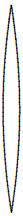
Figure \( 11.29\):
\(h\) can be ignored just like other corrections to small angle relations (like \(\sin \theta \approx \theta\)).
Putting together the geometry from Figure \( 11.28\) with the formula for \(\delta\) in a prism, we get the constant \(f\) for a thin spherical lens: \[\begin{gathered}
\delta=(n-1)\left(\theta_{1}+\theta_{2}\right) \\
\approx(n-1)\left(\frac{h}{r_{1}}+\frac{h}{r_{2}}\right)=\frac{h}{f}
\end{gathered}\]
and thus \[\frac{1}{f}=(n-1)\left(\frac{1}{r_{1}}+\frac{1}{r_{2}}\right)\]
This is called the “lens-maker’s formula”
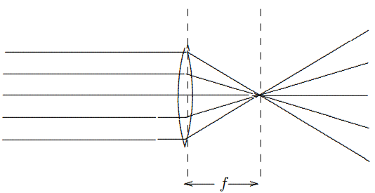
Figure \( 11.30\):
A lens of this kind focuses parallel rays of light, as shown in Figure \( 11.30\). This works because \(\delta \approx h / f\) as shown in Figure \( 11.31\). Parallel rays at any angle are focused onto a “focal plane” a distance \(f\) from the lens as shown in Figure \( 11.32\). The analytical way of explaining how this works is to note that the difference in the slopes of the rays on the two
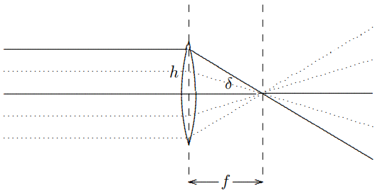
Figure \( 11.31\):
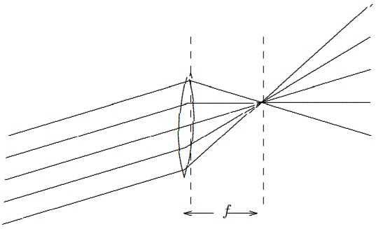
Figure \( 11.32\):
sides of the lens is proportional to the height. Thus the in this case, because the slopes on one side are the same, the difference in slopes on the other side is proportional to the difference in height, and that means that they all come together at the same \(x\).
Another way to see that this focusing must work is illustrated in \(Figures \text { } 11.33\) and \(11.34\). Note that if the parallel rays are coming in at an angle \(\delta_{i}\), the ray a distance \(h_{i}=\delta f\) above the center of the lens is bent to the horizontal, as shown in Figure \( 11.33\) with the solid line. Then for the rays on either side of that ray (shown as dashed lines), because the dependence of the bending on the height in the lens is linear, the total angular bend, \(\delta_{i}+\delta_{o}\) is \(f\) multiplied by the total distance from the center, \(h_{i}+h_{o}\), but then \(h_{o}=\delta_{o} f\), which is the condition for focusing. This is illustrated in Figure \( 11.34\).
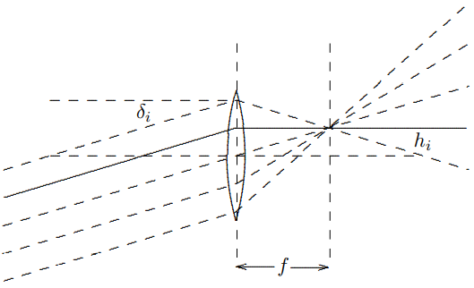
Figure \( 11.33\):
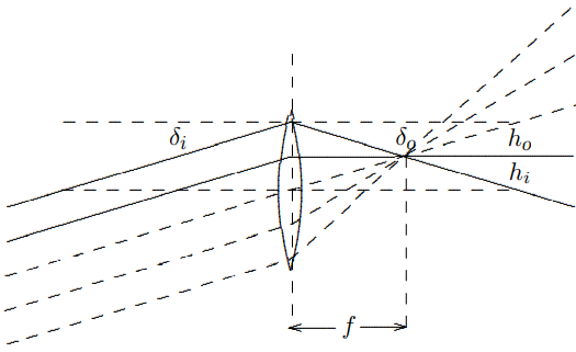
Figure \( 11.34\):
For a bundle of parallel rays at any angle, you can determine where they hit the focal plane by tracing any ray, the easiest being the one through the center of the lens, which is not bent at all, as shown in Figure \( 11.35\). The parallel rays (a part of a plane wave — we know this is impossible, but we are ignoring diffraction) can be thought of as coming from a point source at infinity. If there is a point source closer to the lens, it focuses farther away. Now play with the animation LENS.EXE.
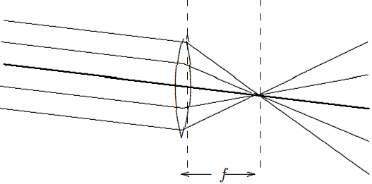
Figure \( 11.35\):
To find the relation between \(d_{1}\) and \(d_{2}\), consider the diagram in Figure \( 11.37\) — the sum of the angles of deflection on the two sides equals \(\delta\): \[\delta_{1}+\delta_{2}=\delta\]
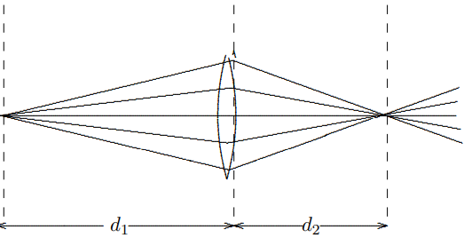
Figure \( 11.36\):
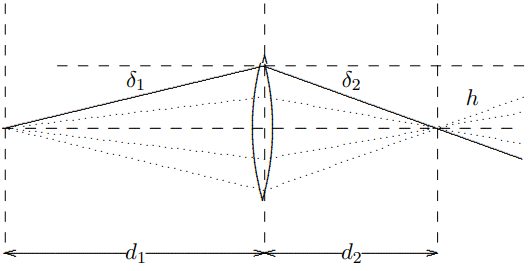
Figure \( 11.37\):
which for small angles is equivalent to \[\frac{h}{d_{1}}+\frac{h}{d_{2}}=\frac{h}{f}\]
or \[\frac{1}{d_{1}}+\frac{1}{d_{2}}=\frac{1}{f}\]
This is called the “thin lens formula.”
So far, we have discussed “converging” or “convex” lenses for which \(f\) is positive, but there are also “diverging” or “concave” lenses, for which \(f\) is negative. In this case, parallel rays are not focuses, but defocused, and appear to diverge from a plane a distance −\(f\) (which is a positive number) beyond the lens, as shown in Figure \( 11.38\): The point from which the
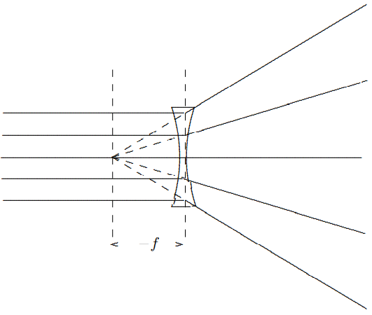
Figure \( 11.38\):
outgoing rays diverge is called a “virtual image.” In this case it is a virtual image of the point at infinity. Shown in Figure \( 11.39\) is the effect of a concave lens on a point source. Again there is a virtual image. Here the thin lens formula is still satisfied, but both \(f\) and \(d_{2}\) are negative.
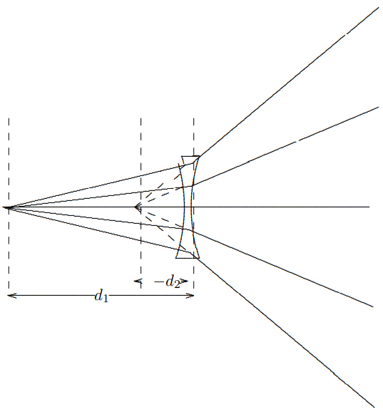
Figure \( 11.39\):
Images
The focusing property of a lens can be used to project an image of an object on a surface, as shown in Figure \( 11.40\). What is happening is that light fanning out from each point on
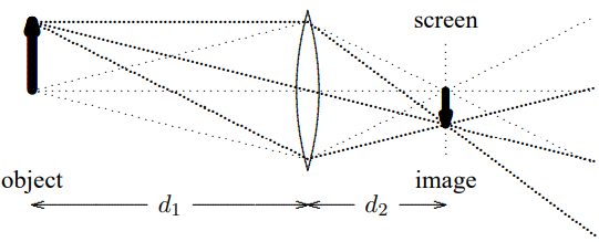
Figure 11.40:
the object is focused back to a single point on the screen. As in \(Figures \text { } 11.36\) and \(11.37\), the distances satisfy the thin lens formula, \[\frac{1}{d_{1}}+\frac{1}{d_{2}}=\frac{1}{f}\]
This tell you where to put the screen. Note also that it is easy to see where on the screen the image of a particular point on the object appears because a ray of light that goes right through the center of the lens is not deflected at all (we also used this for parallel rays above Figure \( 11.35\)). This plus simple geometry then implies that the ratio of the size of the image to the size of the object is \(d_{2} / d_{1}\). \[\frac{\text { size of image }}{\text { size of object }}=\frac{d_{2}}{d_{1}}\]
If the screen in Figure \( 11.40\) is removed, you can see that the light to the right of where the screen was is a copy of the light coming from the object, but upside down, and changed in size by \(d_{2} / d_{1}\). If you have played with lenses, you know this.
Notice that (11.153) implies that neither \(d_{1}\) nor \(d_{2}\) can be less that \(f\). If you bring the object too close to the lens, you do not get a real image on the other side. Instead, \(d_{2}\) becomes negative and you get a “virtual image” on the same side of the lens as the object, and the light to the right of the lens is diverging as if it came from the virtual image. This situation is illustrated in Figure \( 11.41\). As we will discuss further below, this is how a magnifying glass works.
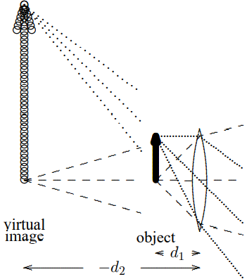
Figure \( 11.41\):
The image formation illustrated in Figure \( 11.40\) is what happens in a camera, and in your own eyeball. The lens focuses light from outside points onto points on the film, or your retina. Of course, the retina is not actually a plane. For the same reason, your eye lens is not a spherical lens, but some more complicated shape instead. The ray tracing has been done by evolution, however, so that objects in a plane get focused properly onto the retina.
Because the distance from your eye lens to your retina is fixed by the geometry of your eye, you must be able to adjust the shape of your lens. By doing so, you can change the focal length of your lens and thus change the distance at which points are perfectly in focus (this is called “accommodation”).
The formation of an image on your retina is illustrated in the diagram in Figure \( 11.42\). Again as in Figure \( 11.40\) the image is upside down. You cannot focus on objects that are too
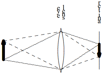
Figure \( 11.42\):
close to your eye lens because the amount of accommodation you can do is limited. If you bring the object too closer than the smallest focal length your eye lens can produce, the real image is beyond your retina, the object will look fuzzy, as shown in Figure \( 11.43\).
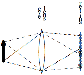
Figure \( 11.43\):
A magnifying glass works by allowing you to produce a larger image of the object on your retina. It does this in two ways, both of which are illustrated in the diagram in Figure \( 11.44\) (with fewer light rays shown now because the diagrams are getting too busy).
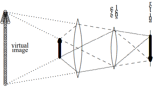
Figure \( 11.44\):
Obviously, the image is larger. But note also that the magnifying glass changes the amount of accommodation required by your eye lens. Your eye is actually focusing on the virtual image which is much farther away, and that is easier. Thus when you look at an object in a magnifying glass, you can bring it much closer to your eye then you could without the glass. This further increases the magnifying effect, because closer objects look bigger. In this diagram you can also see a third salutary effect of the magnifying glass — more of the light from the object reaches your eye.
One of the magnifying effects of a lens can be obtained without a lens in a very simple way — with a pinhole. If you look at a nearby object through a pinhole, you can bring it
much closer to your eye. The reason is that only a narrow beam of light get through the pinhole from each point on the object you are looking at, so not much focusing is required. The size of the image on your retina is not increased when you look at the object through a pinhole at the same same distance as without the pinhole, but with the pinhole, you can bring it much closer to your eye without fuzziness, and therefore you make it appear bigger.
You may also have played with pinhole cameras, in which you form an image on a screen in a dark box without a lens, as shown in Figure \( 11.45\).
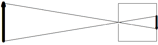
Figure \( 11.45\):
One disadvantage to a pinhole camera is that you need a very bright object. You throw away most of the light coming from the object. You can get more light by making the pinhole larger, but that makes the image fuzzier. Actually, however, you cannot make the pinhole too small anyway. Ultimately, as we will see in chapter 13, diffraction limits the resolution of a pinhole camera. If you try to make the image very sharp by making the pinhole very tiny, the beam you get inside the camera will be spread by diffraction. The best you can do is choose
the size of your pinhole so that the spreading at the screen due to diffraction just matches the size of the pinhole.
While we are on the subject, note that diffraction and the finite size of your pupil limits the angular resolution of your eye. As we will understand in detail in chapter 13, the finite size, \(s\) of your pupil introduces an angular spread of order \(d / \lambda\) for light of wavelength \(\lambda\). Unless you have huge eyes, \(s\) is less than .25 cm, so for green light with wavelength 500 nanometers (550 is about the middle of the visible spectrum), the angular resolution is greater than about 2 × 10⁻⁴. At a distance of 10 meters, for example, even if your eyes are perfect, you will not be able to resolve two objects less than a few millimeters apart.
You can use a pinhole to study your eyes in rather interesting ways. Put the pinhole close to your eye and look at a bright diffuse source of light. We will do this in lecture, but you can make your own pinhole by punching a small hole in a piece of aluminum foil with a pin and try this out. If you wear glasses, take them off. You won’t need them. You should see a circular spot of light. This is the image of your pupil on your retina, as shown below:
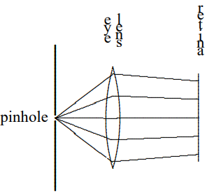
Figure \( 11.46\):
You can watch the size of your pupil change with this arrangement. Just cover or close your other eye. Because you are now getting less light, both pupils will expand. Uncover the other eye and look at the bright light again and the pupils will contracts. Can you notice a short time-lag?
Now carefully bring a pen or pencil point up from below in between the pinhole and your eye, until it just begins to obscure your view. What do you see? This should convince you, if you were not sure before, that the image on your retina is upside down, as shown in Figure \( 11.47\). The bottom half of the image on your retina is missing. Your brain, being used
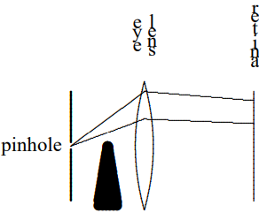
Figure \( 11.47\):
to seeing images on the retina upside down, interprets this as an object coming down from above!
Magnification, telescopes, microscopes, and all that
By combining lenses in various ways, you can construct all sorts of interesting optical instruments. The simplest way to think about magnification is just to consider the angular size of the observed image, compared to the angular size you would see without the instrument.
A simple telescope is illustrated in Figure \( 11.48\). The distances are somwhat distorted. In a real telescope the object would be much farther way and the sizes of the lenses much smaller. When you look at a distant object (large \(L\)) with your telescope, the light arrives at the first (“objective”) lens as a nearly parallel bundle of rays. We know from the thin lens formula \[\frac{1}{d_{1}}+\frac{1}{d_{2}}=\frac{1}{f}\]
with \(d_{1}=L \gg f\) that a real image forms at a distance from the objective \(d_{2}\) just slightly larger than its focal length \(f_{1}\). The “eyepiece” is then placed a distance just beyond its focal length, \(f_{2}\), from the real image, to make the light from the image into a nearly parallel bundle
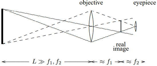
Figure \( 11.48\):
again. Essentially what you are doing with the eyepiece is looking at the light from the real image with a magnifying glass.
We can understand how (and how much) a telescope magnifies distant objects by looking at the angles involved. If the object has size \(h_{o}\), its angular size without the telescope is \[\frac{h_{o}}{L+f_{1}+f_{2}} \approx \frac{h_{o}}{L}\]
By similar triangles, the size of the real image is \[\frac{h_{o}}{L} \cdot f_{1}\]
and thus the angular size of the real image at the eyepiece (and your eye) is \[\frac{h_{o}}{L} \cdot \frac{f_{1}}{f_{2}}\]
Thus the magnification is approximately \[\frac{f_{1}}{f_{2}}\]
Note that the telescope image appears upside down because what you are actually seeing is the real image.
A microscope looks something like what is shown in Figure \( 11.49\) (with even fewer light rays drawn because you should be getting used to them by this time.
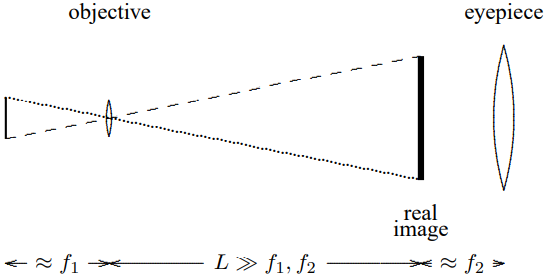
Figure \( 11.49\):
The sample is placed just a little more than the focal length, \(f_{1}\), away from the objective so that a real image forms that is much bigger than the sample. Then you look at the real image with the eyepiece as a magnifying glass, again positioned a little more than its focal length, \(f_{2}\), away, to be able to view the image comfortably with your eyes relaxed. If the sample has size \(h_{o}\), the size of the real image is \[\frac{L}{f_{1}} \cdot h_{o}\]
and the angular size of the image at the eyepiece (and your eye) is \[\frac{L h_{o}}{f_{1} f_{2}}\]
This should be compared with the angular size of the object at some reference length, \(L_{0} \approx 25 \mathrm{~cm}\), at which you can view the object comfortably with your unaided eye, which is \[\frac{h_{o}}{L_{0}}\]
Thus the magnification is \[\frac{L L_{0}}{f_{1} f_{2}}\]