
13.10: 13-8- Holography


- Last updated
- Aug 2, 2021
- Save as PDF

( \newcommand{\kernel}{\mathrm{null}\,}\)
Nothing prevents us from doing the analysis of a diffraction pattern from a more complicated function, f(x, y), than that discussed in (13.16). A hologram is just such a diffraction pattern. One of the simplest versions of a hologram is one in which an object is illuminated by a laser, that provides essentially a plane wave. The reflected light, and a part of the laser beam (extracted by some beam splitting technique) are incident on a photographic plate at slightly different angles, as shown schematically in Figure 13.31. The wave incident on the photographic plate has the form e^{-i \omega t}\left(e^{i k z}+\int d k_{x} d k_{y} C\left(k_{x}, k_{y}\right) e^{i \vec{k} \cdot \vec{r}}\right)
where k=|\vec{k}|=\omega / v.
(13.127) describes the two coherent parts of the light wave incident on the photographic plate. For simplicity, we will assume that the signal in which we are actually interested, the reflected wave with Fourier transform C(k_{x}, k_{y}), is small compared to the reference wave e^{i k z}. This signal is what we would see if the photographic plate were removed and we placed
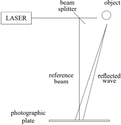
Figure 13.31: Making a hologram.
our eyes in the path of the reflected wave, but out of the path of the laser beam, as shown in Figure 13.32.
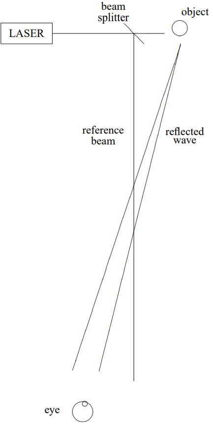
Figure 13.32: Viewing the object.
The photographic plate (we’ll assume it’s at z = 0) records only the intensity of the total wave, proportional to 1+2 \operatorname{Re} \int d k_{x} d k_{y} C\left(k_{x}, k_{y}\right) e^{i\left(k_{x} x+k_{y} y\right)}+\mathcal{O}\left(C^{2}\right)
We will drop the terms of order C^{2}, assuming that C is small, although we will be able to see later that they will not actually not make any difference even if C is large. If we now make a positive slide from the plate and shine through it a laser beam with the same frequency, \omega, the wave “gets through” where the light intensity on the plate was large and is absorbed where the intensity was small. Thus we have a forced oscillation problem of exactly the sort that we discussed above, with (13.129) playing the role of f(x, y). The solution for z > 0 (from (13.19)-(13.24)) is e^{-i \omega t}\left(e^{i k z}+\int d k_{x} d k_{y} C\left(k_{x}, k_{y}\right) e^{i \vec{k} \cdot \vec{r}}+\text { c.c. }\right)\]
where c.c. is the complex conjugate wave obtained by taking the complex conjugate of the signal and changing the sign of the z dependence to get a wave traveling in the +z direction. The important thing to note about the complex conjugate wave is that it represents a beam traveling in a different direction from either the signal or the reference beam, because the complex conjugation has changed the sign of k_{x} and k_{y}.
The resulting system is shown schematically in Figure 13.33. Your eye sees a reconstructed version of the reflected wave that you would have seen without the photographic plate, as in (13.32). Note that neither the reference beam nor the complex conjugate beam get in the way of your viewing, because they go off at slightly different angles. This is a hologram. Because it is not a picture but a reconstruction of the actual wave that you would have seen in (13.32), it has the surprising property of three-dimensionality that makes a hologram striking.
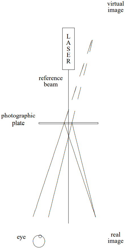
Figure 13.33: Viewing the holographic image.
One might wonder why we choose the angle between the reference beam and the signal to be small. A large angle would have the advantage of getting the reference beam farther out of the way, but it would have an important disadvantage. Consider the intensity pattern on the photographic plate that records the hologram. It is an oscillating pattern with a typical wave number given by the typical value of k_{x} or k_{y}. These are of order k \sin \theta, where \theta is the angle between the reference beam and the signal. But the distance between neighboring maxima on the photographic plate is therefore of order \frac{2 \pi}{k \sin \theta}=\frac{\lambda}{\sin \theta}
where \lambda is the wavelength of the light. Since \lambda is a very small distance, it pays to pick \theta small to spread out the pattern on the photographic plate.
Note, also, that the order C^{2} terms that we dropped really don’t do any harm even if C is not small. Because their x and y dependence is proportional to that of the signal times its complex conjugate, the typical k_{x} and k_{y} for these terms is zero and they travel roughly in the direction of the reference beam. They don’t reach your eye in (13.33).