
4.5: Applications of Electric Potential and Conductors in Electrostatic Equilibrium


- Last updated
- Jul 15, 2025
- Save as PDF
( \newcommand{\kernel}{\mathrm{null}\,}\)
Learning Objectives
By the end of this section, you will be able to:
- Define grounding and bonding.
- Identify some effects of electricity on the human body and their implications for electrical safety.
- Describe the electric field surrounding Earth.
- Explain how a lightning rod works.
- Define screening, and explain how a Faraday cage works.
Applications of Electric Potential and Field
There are numerous practical applications of electric potential and electric field in the practice of Amateur Radio and other wireless technology. We highlight a few important examples in this section.
Grounding and Bonding
With respect to electricity, a ground is considered a reference point in an electrical circuit from which voltages are measured [1]. The term "ground" is used because, it is common to make physical connections to the Earth, often by a metal stake placed in ground (Fig. 4.5.1), via a conductor. From Conductors in Electrostatic Equilibrium, we know that a conductor will have a constant potential. If multiple connections are made to ground via conductors, then they will all share the same potential. It is conventional to set the potential to zero volts for convenience. The process of connecting a circuit to ground is called grounding. Bonding is the process of connecting together multiple electrical devices with a conductor, usually a thick wire, to maintain a constant potential among the devices, and is often done before connecting the devices to ground.

Proper grounding and bonding are important for electrical safety. For example, grounding the metal case of an electrical appliance ensures that it is at zero volts relative to Earth. This practice can minimize the chance of electric shock hazards when a fault occurs in the wiring. Grounding can also help to minimize potential differences between devices during sudden changes in voltage in the electrical distribution system. During lighting strikes, it can also help to dissipate charge, routing away from valuable equipment and into the Earth. While these processes sound simple enough, there can be subtleties when implementing them in practice. You should follow the grounding requirements in your local electrical codes, particularly for Amateur Radio towers and antennas. (See Ref [2] for a comprehensive discussion of best practices for grounding and bonding for Amateur Radio.)
Electrophysiology
Electrophysiology is a branch of physiology that studies the electrical properties of cells and tissue. The human body contains several systems that use electrical signals. For example, the heart relies on electrical signals to maintain its rhythm [4]. The movement of electrical signals causes the chambers of the heart to contract and relax. The equipotential lines around the heart and surrounding areas are useful ways of monitoring the structure and functions of the heart. An electrocardiogram (ECG) measures the small electric signals being generated during the activity of the heart. When a person has a heart attack, the movement of these electrical signals may be disturbed. When a person has irregular heartbeat, an artificial pacemaker and a defibrillator can be used to initiate the rhythm of electrical signals. Electrical signals also play an important role in the nervous system. Like cardiac tissue, nerves are also capable of transmitting electrochemical nerve impulses called action potentials (voltages) along the body of the nerve cells [5] (Fig. 4.5.2).
Human electrophysiology has implications for electrical safety. As we will see, electrical charges will move from regions of high electrical potential to regions of low potential (ground). When touching electrical circuits, you want to ensure you do not become the path to ground! One good practice is only to touch circuits at one point. (Keep your other hand in a pocket!) In particular, avoid allowing charge to move in a path across the heart, for example, from one hand to the other. Electric shocks can also cause nervous system responses, including involuntary muscle contractions. In the worst cases, these contractions are so strong that they may prevent you from releasing from the charged object, making it difficult to remove yourself from the hazard! As will be discussed later, electrical shocks may also cause heating or burning of tissue. Other common safety practices include removing metal jewelry, working in dry conditions, and being aware of overhead wires.
Earth’s Electric Field
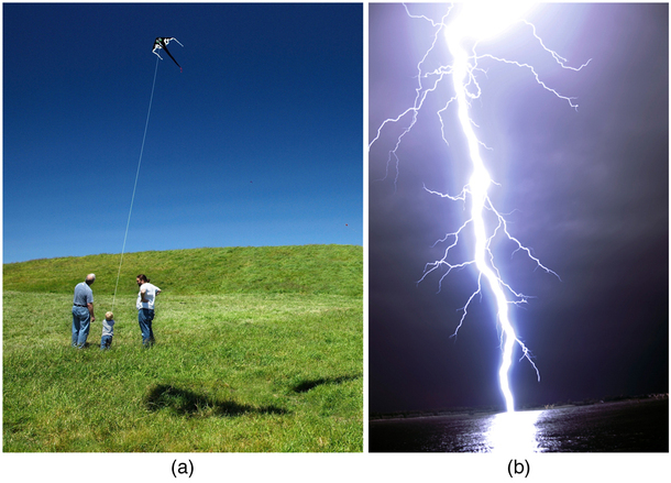
A near uniform electric field of approximately 100 to 150 N/C, directed downward, surrounds Earth, with the magnitude increasing slightly as we get closer to the surface. What causes the electric field? At around 100 km above the surface of Earth, we have a layer of charged particles, called the ionosphere. The ionosphere is predominantly caused by ultraviolet radiation from the sun. The ionosphere is responsible for a range of interesting phenomena, including the electric field surrounding Earth and the bending of radio waves. In fair weather, the ionosphere is positive and the Earth largely negative, maintaining the electric field (Figure 4.5.3a) [7] .
In storm conditions, clouds form, and localized electric fields can be larger and even reversed in direction (Figure 4.5.3b). The exact charge distributions depend on the local conditions, and variations of Figure 4.5.2b are possible. If the electric field is sufficiently large, the insulating properties of the surrounding material experience electrical breakdown, and it becomes conducting. For air, breakdown starts to occur at around 3×10⁶ N/C. The field ionizes the air, and electrons can move through the air, resulting in effects like lightning [8, 9] and corona discharge [10].
Applications of Conductors
Lightning Rods
As discussed in Conductors in Electrostatic Equilibrium, a charged conductor will have a higher electric field and surface charge density where it has higher curvature. A practical application of this phenomenon is the lightning rod, which is simply a grounded metal rod with a sharp end pointing upward (Fig. 4.5.4, 4.5.5a). As positive charge accumulates in the ground due to a negatively charged cloud overhead, the electric field around the sharp point gets very large. When the field reaches a value of approximately 3.0×10⁶N/C (the dielectric strength of the air), the free ions in the air are accelerated to such high energies that their collisions with air molecules actually ionize the molecules. The resulting free electrons in the air then flow through the rod to Earth, thereby neutralizing some of the positive charge. This keeps the electric field between the cloud and the ground from getting large enough to produce a lightning bolt in the region around the rod.
Lightning protection is an important part of the safety considerations for Amateur Radio operators, who often have tall antennas or towers to improve their ability to transmit and receive radio signals. As the height of an antenna or tower increases, so does its probability of being struck. The risk level also depends on the prevalence of thunderstorms in the vicinity. This property of conductors must also be considered when performing the grounding of a lightning rod. The connections from the rod should be as short and direct as possible and should not connect sharp angles that could result in the electric charges arcing through the air prior to reaching ground.
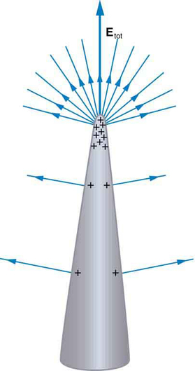
Figure 4.5.4: A very pointed conductor has a large charge concentration at the point. The electric field is very strong at the point and can exert a force large enough to transfer charge on or off the conductor. Lightning rods are used to prevent the buildup of large excess charges on structures and, thus, are pointed.
It is possible to create maps of lightning activity in near real-time. Each time a lightning strike occurs, very low frequency (VLF) radio waves (3 to 30 kHz) are emitted. By detecting these signals at multiple receiving stations at known locations, it is possible to triangulate the location of the lightning strike [11]. See the maps at Blitzortung.org [12] for examples in your region.
Of course, we sometimes wish to prevent the transfer of charge rather than to facilitate it. In that case, the conductor should be very smooth and have as large a radius of curvature as possible (Figure 4.5.5b). For example, smooth surfaces are used on high-voltage transmission lines to avoid leakage of charge into the air.
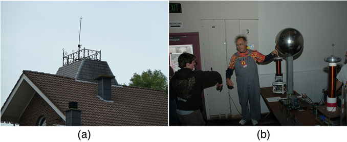
Figure 4.5.5: (a) A lightning rod is pointed to facilitate the transfer of charge. (credit: Romaine, Wikimedia Commons) (b) This Van de Graaff generator has a smooth surface with a large radius of curvature to prevent the transfer of charge and allow a large voltage to be generated. The mutual repulsion of like charges is evident in the person’s hair while touching the metal sphere. (credit: Jon ‘ShakataGaNai’ Davis/Wikimedia Commons).
Screening
We also learned in Conductors in Electrostatic
By similar reasoning, the body of your car can serve as a partial Faraday cage. As a result, if you are driving a car during an electrical storm, it is best to stay inside the car. Even if the car is in the vicinity of a lightning strike, the effect of the strike will be felt on the outside of the car. You will be unaffected, provided you remain totally inside and not in contact with the body of vehicle. This protective effect is also true if an active (“hot”) electrical wire breaks in a storm or an accident and falls on the car.
Amateur radio operators will use screening to try to protect their radio equipment from interference from surrounding devices. Some cables, like the coaxial cables used in radio and cable television, also use screening to minimize the effects of surrounding electrical noise. The American Radio Relay League headquarters contains a Faraday cage used to test radio equipment without outside interference. However, the screening effects can also be detrimental to radio reception. For example, it can sometimes be difficult to get good reception inside a vehicle using a handheld VHF transceiver with a directly-mounted antenna (see photo in Amateur Radio Equipment Basics). Instead, the antenna should be placed on the exterior of the vehicle and then connected to the radio via a transmission cable.
References
- Wikipedia contributors. Ground (electricity) [Internet]. Wikipedia, The Free Encyclopedia.
- Silver, HW (N0AX). Grounding and bonding for the radio amateur: Good practices for electrical safety, lightning protection, and RF management, 2nd edition. Newington, CT: American Radio Relay League; 2021.
- Wikimedia Commons contributors. File:HomeEarthRodAustralia1.jpg [Internet]. Wikimedia Commons. (Ali K., CC-BY-SA 3.0)
- Wikipedia contributors. Cardiac conduction system [Internet]. Wikipedia, The Free Encyclopedia.
- Wikipedia contributors. Nerve [Internet]. Wikipedia, The Free Encyclopedia.
- Wikimedia Commons contributors. File:Action Potential.gif [Internet]. Wikimedia Commons. (Laurentaylorj, CC-BY-SA 3.0)
- Wikipedia contributors. Atmospheric electricity [Internet]. Wikipedia, The Free Encyclopedia.
- Wikipedia contributors. Lightning [Internet]. Wikipedia, The Free Encyclopedia.
- JetStream - An Online School for Weather. Lightning: introduction to lightning. [Internet] National Oceanic and Atmospheric Administration.
- Wikipedia contributors. Corona discharge [Internet]. Wikipedia, The Free Encyclopedia.
- Lightningmaps.org. Lightning detection [Internet]. Lightningmaps.org.
- Blitzortung.org. Overview map [Internet]. Blitzortung.org.
- Wikipedia contributors. Faraday cage [Internet]. Wikipedia, The Free Encyclopedia.
- Wikimedia Commons contributors. File:Faraday cage.gif [Internet]. Wikimedia Commons. (Stanisław Skowron, public domain)
Technician Exam Questions
Relevant exam questions include: T9A07, T0A02, T0A09, T0B01, T0B10, T0B11