11.4: Conductors and Infinite Conducting Plates
- Page ID
- 80074
\( \newcommand{\vecs}[1]{\overset { \scriptstyle \rightharpoonup} {\mathbf{#1}} } \)
\( \newcommand{\vecd}[1]{\overset{-\!-\!\rightharpoonup}{\vphantom{a}\smash {#1}}} \)
\( \newcommand{\dsum}{\displaystyle\sum\limits} \)
\( \newcommand{\dint}{\displaystyle\int\limits} \)
\( \newcommand{\dlim}{\displaystyle\lim\limits} \)
\( \newcommand{\id}{\mathrm{id}}\) \( \newcommand{\Span}{\mathrm{span}}\)
( \newcommand{\kernel}{\mathrm{null}\,}\) \( \newcommand{\range}{\mathrm{range}\,}\)
\( \newcommand{\RealPart}{\mathrm{Re}}\) \( \newcommand{\ImaginaryPart}{\mathrm{Im}}\)
\( \newcommand{\Argument}{\mathrm{Arg}}\) \( \newcommand{\norm}[1]{\| #1 \|}\)
\( \newcommand{\inner}[2]{\langle #1, #2 \rangle}\)
\( \newcommand{\Span}{\mathrm{span}}\)
\( \newcommand{\id}{\mathrm{id}}\)
\( \newcommand{\Span}{\mathrm{span}}\)
\( \newcommand{\kernel}{\mathrm{null}\,}\)
\( \newcommand{\range}{\mathrm{range}\,}\)
\( \newcommand{\RealPart}{\mathrm{Re}}\)
\( \newcommand{\ImaginaryPart}{\mathrm{Im}}\)
\( \newcommand{\Argument}{\mathrm{Arg}}\)
\( \newcommand{\norm}[1]{\| #1 \|}\)
\( \newcommand{\inner}[2]{\langle #1, #2 \rangle}\)
\( \newcommand{\Span}{\mathrm{span}}\) \( \newcommand{\AA}{\unicode[.8,0]{x212B}}\)
\( \newcommand{\vectorA}[1]{\vec{#1}} % arrow\)
\( \newcommand{\vectorAt}[1]{\vec{\text{#1}}} % arrow\)
\( \newcommand{\vectorB}[1]{\overset { \scriptstyle \rightharpoonup} {\mathbf{#1}} } \)
\( \newcommand{\vectorC}[1]{\textbf{#1}} \)
\( \newcommand{\vectorD}[1]{\overrightarrow{#1}} \)
\( \newcommand{\vectorDt}[1]{\overrightarrow{\text{#1}}} \)
\( \newcommand{\vectE}[1]{\overset{-\!-\!\rightharpoonup}{\vphantom{a}\smash{\mathbf {#1}}}} \)
\( \newcommand{\vecs}[1]{\overset { \scriptstyle \rightharpoonup} {\mathbf{#1}} } \)
\(\newcommand{\longvect}{\overrightarrow}\)
\( \newcommand{\vecd}[1]{\overset{-\!-\!\rightharpoonup}{\vphantom{a}\smash {#1}}} \)
\(\newcommand{\avec}{\mathbf a}\) \(\newcommand{\bvec}{\mathbf b}\) \(\newcommand{\cvec}{\mathbf c}\) \(\newcommand{\dvec}{\mathbf d}\) \(\newcommand{\dtil}{\widetilde{\mathbf d}}\) \(\newcommand{\evec}{\mathbf e}\) \(\newcommand{\fvec}{\mathbf f}\) \(\newcommand{\nvec}{\mathbf n}\) \(\newcommand{\pvec}{\mathbf p}\) \(\newcommand{\qvec}{\mathbf q}\) \(\newcommand{\svec}{\mathbf s}\) \(\newcommand{\tvec}{\mathbf t}\) \(\newcommand{\uvec}{\mathbf u}\) \(\newcommand{\vvec}{\mathbf v}\) \(\newcommand{\wvec}{\mathbf w}\) \(\newcommand{\xvec}{\mathbf x}\) \(\newcommand{\yvec}{\mathbf y}\) \(\newcommand{\zvec}{\mathbf z}\) \(\newcommand{\rvec}{\mathbf r}\) \(\newcommand{\mvec}{\mathbf m}\) \(\newcommand{\zerovec}{\mathbf 0}\) \(\newcommand{\onevec}{\mathbf 1}\) \(\newcommand{\real}{\mathbb R}\) \(\newcommand{\twovec}[2]{\left[\begin{array}{r}#1 \\ #2 \end{array}\right]}\) \(\newcommand{\ctwovec}[2]{\left[\begin{array}{c}#1 \\ #2 \end{array}\right]}\) \(\newcommand{\threevec}[3]{\left[\begin{array}{r}#1 \\ #2 \\ #3 \end{array}\right]}\) \(\newcommand{\cthreevec}[3]{\left[\begin{array}{c}#1 \\ #2 \\ #3 \end{array}\right]}\) \(\newcommand{\fourvec}[4]{\left[\begin{array}{r}#1 \\ #2 \\ #3 \\ #4 \end{array}\right]}\) \(\newcommand{\cfourvec}[4]{\left[\begin{array}{c}#1 \\ #2 \\ #3 \\ #4 \end{array}\right]}\) \(\newcommand{\fivevec}[5]{\left[\begin{array}{r}#1 \\ #2 \\ #3 \\ #4 \\ #5 \\ \end{array}\right]}\) \(\newcommand{\cfivevec}[5]{\left[\begin{array}{c}#1 \\ #2 \\ #3 \\ #4 \\ #5 \\ \end{array}\right]}\) \(\newcommand{\mattwo}[4]{\left[\begin{array}{rr}#1 \amp #2 \\ #3 \amp #4 \\ \end{array}\right]}\) \(\newcommand{\laspan}[1]{\text{Span}\{#1\}}\) \(\newcommand{\bcal}{\cal B}\) \(\newcommand{\ccal}{\cal C}\) \(\newcommand{\scal}{\cal S}\) \(\newcommand{\wcal}{\cal W}\) \(\newcommand{\ecal}{\cal E}\) \(\newcommand{\coords}[2]{\left\{#1\right\}_{#2}}\) \(\newcommand{\gray}[1]{\color{gray}{#1}}\) \(\newcommand{\lgray}[1]{\color{lightgray}{#1}}\) \(\newcommand{\rank}{\operatorname{rank}}\) \(\newcommand{\row}{\text{Row}}\) \(\newcommand{\col}{\text{Col}}\) \(\renewcommand{\row}{\text{Row}}\) \(\newcommand{\nul}{\text{Nul}}\) \(\newcommand{\var}{\text{Var}}\) \(\newcommand{\corr}{\text{corr}}\) \(\newcommand{\len}[1]{\left|#1\right|}\) \(\newcommand{\bbar}{\overline{\bvec}}\) \(\newcommand{\bhat}{\widehat{\bvec}}\) \(\newcommand{\bperp}{\bvec^\perp}\) \(\newcommand{\xhat}{\widehat{\xvec}}\) \(\newcommand{\vhat}{\widehat{\vvec}}\) \(\newcommand{\uhat}{\widehat{\uvec}}\) \(\newcommand{\what}{\widehat{\wvec}}\) \(\newcommand{\Sighat}{\widehat{\Sigma}}\) \(\newcommand{\lt}{<}\) \(\newcommand{\gt}{>}\) \(\newcommand{\amp}{&}\) \(\definecolor{fillinmathshade}{gray}{0.9}\)Electrostatics
Before we discuss the effects of conductors on electric fields, it is essential that we make clear that we are proceeding under the following restriction: We are talking about electrostatics. This means that the charges present are in a state of static equilibrium – they are not moving, nor are they accelerating. We have already said that conductors allow for charges to flow freely, so how can these two things be reconciled?
If a conductor suddenly finds itself in the presence of an electric field, then the charges on that conductor will start to move as a result of the new force. As the charges move, the fields (which are affected by the placement of these charges) also change. The charges continue accelerating until the field contributions of the displaced charges cancel the external field. With zero net field, the charges no longer accelerate, and we will assume that their kinetic energy dissipates such that they also come to rest.
The conclusions we will draw here do not apply to the period of time when the charges are still moving around – we will only be considering the case when the charges finally reach an equilibrium electrostatic state.
Inside Conductors
We characterized electric fields as "signals" sent out by electric charges. This is of course a model (as is all of physics), and this model does not make exceptions that allow for matter to "block" this signal. The only way to affect the field at a point in space caused by one charge is to introduce a field from another charge, such that the two fields superpose.
Let's now consider what happens when we suddenly introduce a uniform external electric field to a rectangular conducting slab. We represent uniform electric fields with parallel, equally-spaced field lines, and as we just said above, these field lines are not interrupted by matter, so the situation looks something like this:
Figure 11.4.1: Conductor Introduced to Field
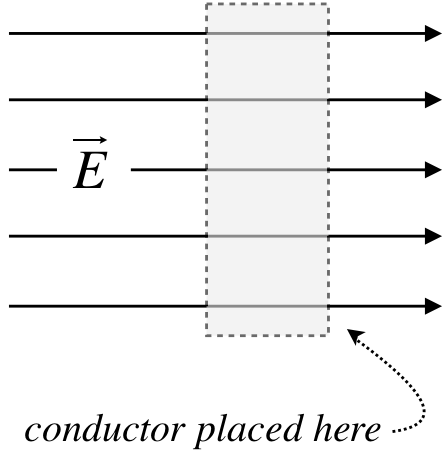
While the conductor is neutrally-charged, it is not without electrical charge – it is made of atoms, which are comprised of protons and electrons. This charge is (by definition of the conductor) free to move. This means that the positive charges in the conductor in the diagram (depicted as red) are pushed to the right by the electric field, while the negative charges (depicted as blue) are pulled to the left.
Figure 11.4.2: Charge Migrated Because of the Applied Field
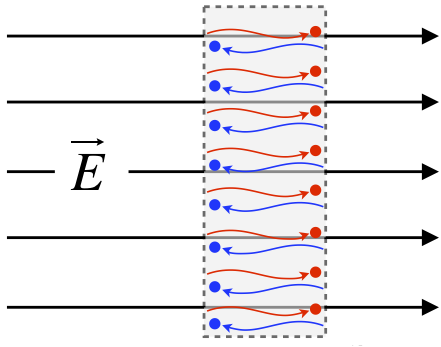
[Okay, so technically only the electrons – the negatively-charged particles – are free to move, or this conductor would not be a solid. This is a distinction that will not be at all important to us, because when negatively-charged electrons vacate a region, they leave an excess of positively-charged protons behind, which is completely equivalent to the positive charge moving into that electron-vacated region.]
The effect of this migration of charge is the creation of two planes of charge, one on each side of the slab (we will always assume that the field is not strong enough to pull the electrons off the surface of the metal). But this separation of charge itself has consequences with regard to the field. In particular, within the metal a new uniform field starts to develop. This field points away from the positive charges toward the negative charges, which opposes the direction of the external field.
Figure 11.4.3: Internal Field Induced by Displayed Charges
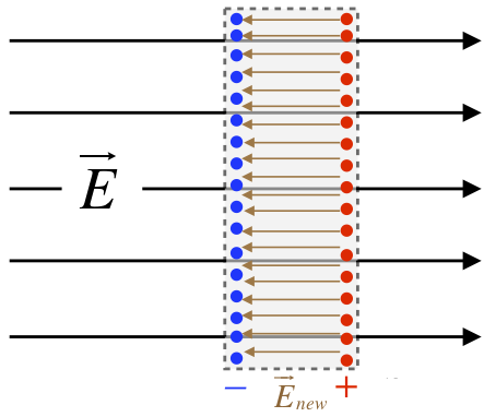
When the field induced within the conductor is superposed with the applied field, the result is a weaker field within the conductor. The question is, how much weaker does it become? Suppose it only becomes a little weaker. That would mean that there is still some net field pointing left-to-right. But if this is the case, then more charge will migrate, making the induced field that points left even stronger, making the superposed field even weaker. In other words, we don't reach electrostatics until enough charge has moved to make the superposed internal field vanish. We therefore get the following remarkably general conclusion:
Electric fields vanish within conductors when the charges are static.
Infinite Conducting Plane
When we looked at point charges we saw that the electric field gets weaker with distance as \(1/r^2\). We also explored superposition where you need to add the electric field from each point charge to obtain the net electric field. Even though the distances to each charge are no longer the same, the net field will still decrease as \(1/r^2\). When the source charges are no longer discrete point charges but a continuous distrubution of charge of a specific shaped, such as a charged rod, a cylinder of a sphere, we can no longer add the field due to each discrete charge in the macroscopic charged object. These calculations are beyond the scope of this course, since sums turn into integral when you go from a discrete collection of charge to a continuous one. For some of the continuous charged distributions, the electric field on longer changes as \(1/r^2\), but still decreases with distance away from the charged object. There is one "special" charge distribution, charge equality distributed on an infinite (extremely) large conducting plane. In this case the electric field is constant around the plate, thus, it does not decrease as you move away from the plane. The electric field files for a positive infinite plane are illustrated below. If the plane was negative, the electric field lines would point toward the plane. From the field lines you can see that the electric field is constant, since the density of file lines does not charge with distance.
Figure 11.4.4: Electric Field around an Infinite Charged Conducting Plate
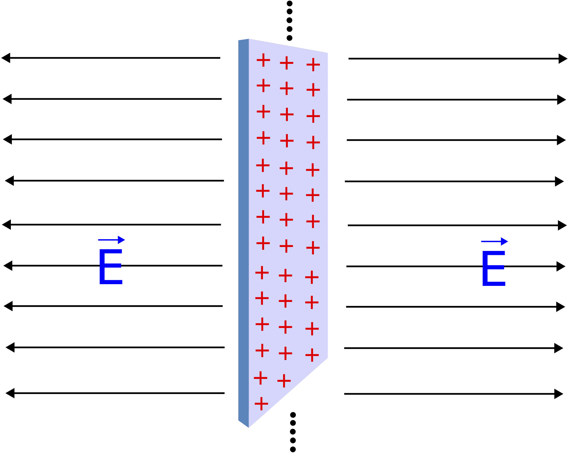
It might seem strange that the electric field is uniform everywhere in space for the infinite plane. Why doesn't the field get stronger closer to the plane of charge? This can be more easily seen using the field line description. If the field got stronger closer to the plane, then the field lines would have to get closer together there. But that can only happen if the field lines are not perpendicular to the plane everywhere. Due to the symmetry of the infinite plane, there is no reason to believe that the field would have any components along the surface of the plane anywhere in space. With the field only pointing along one direction, the field lines can't change their separation, and the field strength remains constant everywhere.
One might ask that although these solutions have simpler forms, how can they be "useful," as claimed above? How many infinite lines or planes of charge does one run across in real life? The answer is that all solutions in physics are approximations, and are only useful up to the sensitivity of the measurements. For example, if we look at the field of a finite-sized plane of charge, but look at a position in space that is very close to the plane compared to the dimensions of that plane, then treating it as "infinite" is a good approximation. What is especially nice about this approximation is that so long as we are looking at positions close to the plane compared to the distance from the edges, we don't even care what shape the plane is – it can be a circular disk, a square, or some random, jagged shape.
Example \(\PageIndex{1}\)
Below are three infinite planes, two positively and one negatively charged with equal magnitude of charge. The separation between the planes is marked below in terms of distance \(d\). A 4C charge which is placed equidistance between the middle positive plane and the negative plane feels a force with magnitude of 10N. Now the 4C charge is removed, and a -5C charge placed a distance \(d\) to the right of the negative plane. Determine the force (magnitude and direction) felt by a -5C charge.
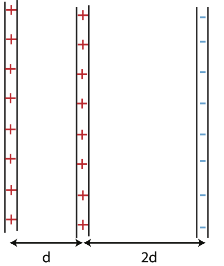
- Solution
-
The electric field is constant for infinite plates. In between the positive and negative plates, the electric field from each one of the two positive plates points to the right, away from the plane. Likewise, the field from the negative plane also and from the negative plates to the left. Since the three planes have equal charge, each one produces an electric field with the same magnitude, \(E\). Thus, the magnitude of total electric field in between the positive and negative planes is:
\[E_{tot}=3E\nonumber\]
The magnitude of the force on a 4C charge placed in between the two plates is:
\[F=qE_{tot}=4C\times 3E=10N\nonumber\]
Solving for the magnitude of the electric field from each plane we get:
\[E=\dfrac{10N}{12C}=\dfrac{5}{6}\dfrac{N}{C}\nonumber\]
On the right of the plates, the electric field from the two positive planes is to the right, but from the negative plane to the left, so the total electric field is to the right:
\[E=2E-E=E=\dfrac{5}{6}\dfrac{N}{C}\nonumber\]
The force on a -5C charge will be to the left:
\[F=qE=-5C\times\dfrac{5}{6}\dfrac{N}{C}=-4.12 N\nonumber\]


