
8.5: Superposition and Interference
- Page ID
- 64284

\( \newcommand{\vecs}[1]{\overset { \scriptstyle \rightharpoonup} {\mathbf{#1}} } \)
\( \newcommand{\vecd}[1]{\overset{-\!-\!\rightharpoonup}{\vphantom{a}\smash {#1}}} \)
\( \newcommand{\dsum}{\displaystyle\sum\limits} \)
\( \newcommand{\dint}{\displaystyle\int\limits} \)
\( \newcommand{\dlim}{\displaystyle\lim\limits} \)
\( \newcommand{\id}{\mathrm{id}}\) \( \newcommand{\Span}{\mathrm{span}}\)
( \newcommand{\kernel}{\mathrm{null}\,}\) \( \newcommand{\range}{\mathrm{range}\,}\)
\( \newcommand{\RealPart}{\mathrm{Re}}\) \( \newcommand{\ImaginaryPart}{\mathrm{Im}}\)
\( \newcommand{\Argument}{\mathrm{Arg}}\) \( \newcommand{\norm}[1]{\| #1 \|}\)
\( \newcommand{\inner}[2]{\langle #1, #2 \rangle}\)
\( \newcommand{\Span}{\mathrm{span}}\)
\( \newcommand{\id}{\mathrm{id}}\)
\( \newcommand{\Span}{\mathrm{span}}\)
\( \newcommand{\kernel}{\mathrm{null}\,}\)
\( \newcommand{\range}{\mathrm{range}\,}\)
\( \newcommand{\RealPart}{\mathrm{Re}}\)
\( \newcommand{\ImaginaryPart}{\mathrm{Im}}\)
\( \newcommand{\Argument}{\mathrm{Arg}}\)
\( \newcommand{\norm}[1]{\| #1 \|}\)
\( \newcommand{\inner}[2]{\langle #1, #2 \rangle}\)
\( \newcommand{\Span}{\mathrm{span}}\) \( \newcommand{\AA}{\unicode[.8,0]{x212B}}\)
\( \newcommand{\vectorA}[1]{\vec{#1}} % arrow\)
\( \newcommand{\vectorAt}[1]{\vec{\text{#1}}} % arrow\)
\( \newcommand{\vectorB}[1]{\overset { \scriptstyle \rightharpoonup} {\mathbf{#1}} } \)
\( \newcommand{\vectorC}[1]{\textbf{#1}} \)
\( \newcommand{\vectorD}[1]{\overrightarrow{#1}} \)
\( \newcommand{\vectorDt}[1]{\overrightarrow{\text{#1}}} \)
\( \newcommand{\vectE}[1]{\overset{-\!-\!\rightharpoonup}{\vphantom{a}\smash{\mathbf {#1}}}} \)
\( \newcommand{\vecs}[1]{\overset { \scriptstyle \rightharpoonup} {\mathbf{#1}} } \)
\(\newcommand{\longvect}{\overrightarrow}\)
\( \newcommand{\vecd}[1]{\overset{-\!-\!\rightharpoonup}{\vphantom{a}\smash {#1}}} \)
\(\newcommand{\avec}{\mathbf a}\) \(\newcommand{\bvec}{\mathbf b}\) \(\newcommand{\cvec}{\mathbf c}\) \(\newcommand{\dvec}{\mathbf d}\) \(\newcommand{\dtil}{\widetilde{\mathbf d}}\) \(\newcommand{\evec}{\mathbf e}\) \(\newcommand{\fvec}{\mathbf f}\) \(\newcommand{\nvec}{\mathbf n}\) \(\newcommand{\pvec}{\mathbf p}\) \(\newcommand{\qvec}{\mathbf q}\) \(\newcommand{\svec}{\mathbf s}\) \(\newcommand{\tvec}{\mathbf t}\) \(\newcommand{\uvec}{\mathbf u}\) \(\newcommand{\vvec}{\mathbf v}\) \(\newcommand{\wvec}{\mathbf w}\) \(\newcommand{\xvec}{\mathbf x}\) \(\newcommand{\yvec}{\mathbf y}\) \(\newcommand{\zvec}{\mathbf z}\) \(\newcommand{\rvec}{\mathbf r}\) \(\newcommand{\mvec}{\mathbf m}\) \(\newcommand{\zerovec}{\mathbf 0}\) \(\newcommand{\onevec}{\mathbf 1}\) \(\newcommand{\real}{\mathbb R}\) \(\newcommand{\twovec}[2]{\left[\begin{array}{r}#1 \\ #2 \end{array}\right]}\) \(\newcommand{\ctwovec}[2]{\left[\begin{array}{c}#1 \\ #2 \end{array}\right]}\) \(\newcommand{\threevec}[3]{\left[\begin{array}{r}#1 \\ #2 \\ #3 \end{array}\right]}\) \(\newcommand{\cthreevec}[3]{\left[\begin{array}{c}#1 \\ #2 \\ #3 \end{array}\right]}\) \(\newcommand{\fourvec}[4]{\left[\begin{array}{r}#1 \\ #2 \\ #3 \\ #4 \end{array}\right]}\) \(\newcommand{\cfourvec}[4]{\left[\begin{array}{c}#1 \\ #2 \\ #3 \\ #4 \end{array}\right]}\) \(\newcommand{\fivevec}[5]{\left[\begin{array}{r}#1 \\ #2 \\ #3 \\ #4 \\ #5 \\ \end{array}\right]}\) \(\newcommand{\cfivevec}[5]{\left[\begin{array}{c}#1 \\ #2 \\ #3 \\ #4 \\ #5 \\ \end{array}\right]}\) \(\newcommand{\mattwo}[4]{\left[\begin{array}{rr}#1 \amp #2 \\ #3 \amp #4 \\ \end{array}\right]}\) \(\newcommand{\laspan}[1]{\text{Span}\{#1\}}\) \(\newcommand{\bcal}{\cal B}\) \(\newcommand{\ccal}{\cal C}\) \(\newcommand{\scal}{\cal S}\) \(\newcommand{\wcal}{\cal W}\) \(\newcommand{\ecal}{\cal E}\) \(\newcommand{\coords}[2]{\left\{#1\right\}_{#2}}\) \(\newcommand{\gray}[1]{\color{gray}{#1}}\) \(\newcommand{\lgray}[1]{\color{lightgray}{#1}}\) \(\newcommand{\rank}{\operatorname{rank}}\) \(\newcommand{\row}{\text{Row}}\) \(\newcommand{\col}{\text{Col}}\) \(\renewcommand{\row}{\text{Row}}\) \(\newcommand{\nul}{\text{Nul}}\) \(\newcommand{\var}{\text{Var}}\) \(\newcommand{\corr}{\text{corr}}\) \(\newcommand{\len}[1]{\left|#1\right|}\) \(\newcommand{\bbar}{\overline{\bvec}}\) \(\newcommand{\bhat}{\widehat{\bvec}}\) \(\newcommand{\bperp}{\bvec^\perp}\) \(\newcommand{\xhat}{\widehat{\xvec}}\) \(\newcommand{\vhat}{\widehat{\vvec}}\) \(\newcommand{\uhat}{\widehat{\uvec}}\) \(\newcommand{\what}{\widehat{\wvec}}\) \(\newcommand{\Sighat}{\widehat{\Sigma}}\) \(\newcommand{\lt}{<}\) \(\newcommand{\gt}{>}\) \(\newcommand{\amp}{&}\) \(\definecolor{fillinmathshade}{gray}{0.9}\) Overview of Superposition
So far in our discussion of waves we analyzed the effect of one source creating a wave pulse, a repeating wave, or a harmonic wave. By knowing the motion and the energy input of the source, we can categorize the shape of the disturbance as it moves with speed determined by the medium. We also looked at the effect of the source and the observer moving. All of these discussions so far assumed one wave source present.
Now we want to explore what happens when two similar waves meet in space. An example of how this could occur is if you and a friend both held a rope. If you wiggle your end, the wave you make will propagate toward your friend. If your friend jiggles her end, her wave will propagate toward you. Another example is dropping two stones nearby in a pond. What happens when the waves collide? Eventually the ripples will overlap, but how can we calculate the resulting displacement from equilibrium? The addition of individual waves to obtain the total effect is called superposition. When waves meet at a given space and time their amplitudes simply add. In the animation below you can see two wave pulses coming together, their displacements adding when they overlap, and continuing to move in the same direction with their original amplitude once they are no longer overlapping.
Figure 8.5.1: Two Pulses Combining
This superposition can only occur with waves of the same type, such as water waves, sound waves, light waves, or waves on a string. Different types of waves can also meet in the same location in space, such as light and sound, but they will not interfere the same way since they are governed by different principles.
For two one-dimensional waves of the same type superposition can be written as:
\[y_{\text{total}}(x,t)=y_1(x,t)+y_2(x,t)\]
The same principles apply to continuous harmonic waves, which specifically can be represented as:
\[y_{\text{total}}=A_1\sin\Phi_1+A_2\sin\Phi_2\label{superposition}\]
Let us look at an example graphically of two waves with the same wavelength and amplitude meeting at the same location in space. Since these waves change with time, we can only look at a snapshot of this occurrence as shown in the figure below. Although, the two waves, \(y_1\) and \(y_2\) overlap in the same location, the wave are plotted separately for clarity.
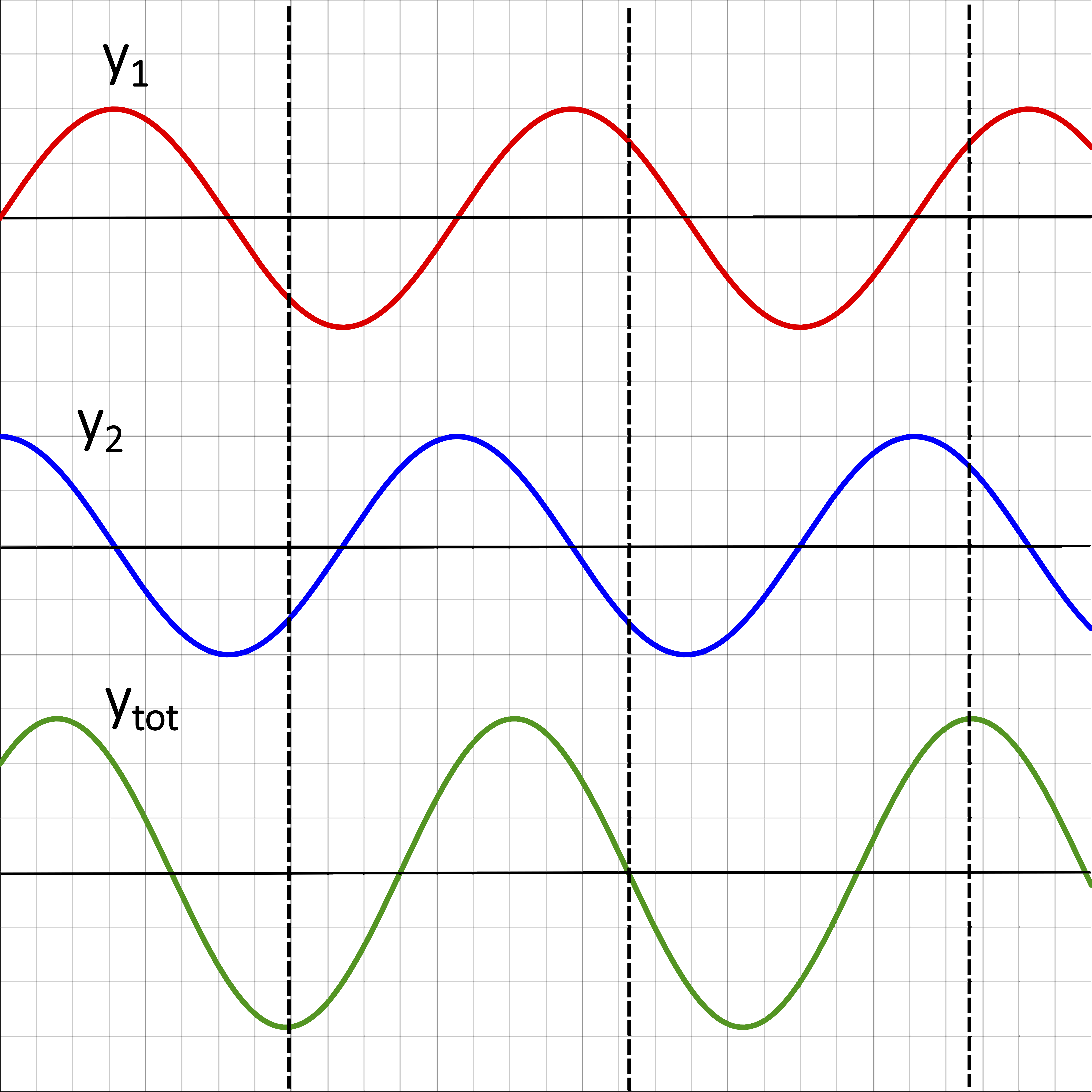
The two top plots are the two individual waves, \(y_1\) and \(y_2\), at some fixed time that meet in the same location in space. The bottom plot, \(y_{\text{tot}}\), is the sum of the the two, which is obtained by summing the displacement of the two individual waves at each location. There are multiple locations marked with the vertical dashed lines which stress the addition of displacements. For example, at the middle dashed line the two displacements add up to zero, since \(y_1\) is positive and \(y_2\) is negative with the same magnitude of displacement. The amplitude of the total wave is clearly not the sum of the amplitudes of the individual ones, since the crests and the troughs do not overlap at any locations. The amplitude is bigger than that of the individual waves, since both waves have an amplitude of two grid lines and the amplitude of the combined wave is close to three grid lines. However, as we will see below this is not always the case. Sometimes the resulting amplitude is less then the either of the individual ones, or in the most extreme case it can be zero.
Special Cases of Interference
The main application of superposition for waves is interference. There are many ways in which any two sinusoidal functions can add, but there are two specific ones which are of special interest. In the left panel of the figure below two waves overlap perfectly. The displacements at each location are identical, so the amplitude of the superimposed wave is sum of the individual amplitude. This case is known as constructive interference. On the other hand, if one wave displaces up while other displaces down, the displacements add up to zero. This is the case of the two waves being half a cycle out of phase, and is known as destructive interference. As can be seen on the right panel of the figure below, the two waves add up to zero everywhere resulting in a complete cancellation of the waves. Partial interference is any kind of interference that isn't completely constructive or completely destructive, as in the example in Figure 8.5.2. The term partial interference is not very descriptive since we can have partial interference that is either almost constructive or almost destructive.
Figure 8.5.3: Constructive and Destructive Interference

As we can see from the examples in figures above, the type of interference that will occur depends on how the two wave line up relative to each other. When crests and troughs meet exactly, the waves are in phase and the resulting amplitude will be the sum of the individual ones. Thus, the total phases of the two waves are the same or different by a multiple of \(2\pi\), which keeps the sine function the same. In other words, the two phases in Equation \ref{superposition} differ only by a factor of \(2\pi n\). If the two initial waves have the same amplitude, then Equation \ref{superposition} for the case of constructive interference becomes:
\[y_{\text{total}}=A\sin\Phi+A\sin(\Phi+2\pi n)=2A\sin\Phi\]
Thus, the new amplitude \(2A\) is double the original one as see on the bottom combined wave in the left plot of Figure 8.5.3 above.
On the other hand, when a crest of one wave overlaps the trough of the other wave, the total phases of the two waves differ by an odd multiple of \(\pi\) resulting in the cancellation of the wave. This is depicted on the right panel of Figure 8.5.3. In this case Equation \ref{superposition} becomes:
\[y_{\text{total}}=A\sin\Phi+A\sin\Big(\Phi+2\pi(n+1/2)\Big)=A\sin\Phi-A\sin\Phi=0\]
where we have used an important property of the sine function, that shifting the phase of the sine function by half a cycle, negates the original function.
From these examples we can see that the difference in the total phase between the two waves determines the type of interference that we observe. For now we will focus on interference between two waves of the same frequency. Since waves interfere in the same medium, this implies that their wavelengths must be the same as well. For interference problems we will always measure position as increasing from the source. In other words, \(x\) is increasing with time, which is equivalent to a right-moving wave. Thus, we will use the minus sign in front of the spatial term in the expression for the total phase defined in a previous section:
\[\Phi = \dfrac{2 \pi}{T}t - \dfrac{2 \pi}{\lambda}x + \phi_o \label{Phi}\]
We can see that there are three terms that can contribute to the difference in the total phase between two waves. Thus, a difference in any of the three terms could determine the difference in the total phase between two waves. Given that we are assuming sources of equal frequencies, a difference in the time-dependent term, \(2\pi\Delta t/T\), could still arise if the interfering sources were turned on at different times. For example, assume that two speakers which are turned on at the same time and are in phase (have the same phase constant), such that they generate crests and troughs at the same time. If instead, you turned on one of the speakers half a period after the other on, then when one speaker is generating a crest the other one would be generating a trough, making them out of phase by half a cycle. However, this scenario is equivalent to two speakers which are turned on at the same time, but with a phase constant difference of half a cycle, \(\Delta\phi_o=\pi\). Thus, you can always account for any difference in time that the waves were generated, as a difference in a phase constant. Therefore, for simplicity we will set the time difference term to zero, \(\Delta t =0\), by always synchronizing the time of the two sources. The total phase difference is then simplified to the following form:
\[\Delta\Phi = - \dfrac{2 \pi}{\lambda}\Delta{x} + \Delta \phi_o \label{dPhi}\]
where the first term depends on the position of each source relative to the location where interference is measured (to be discussed in detail below), and the second term is the difference between the phase constants of the two sources.
The conditions for the the difference in the total phase for different types of interference are as follows:
- Constructive interference: the total phase difference is any even multiple of \(\pi\): \(\Delta\Phi = 2\pi n\), where \(n\) is an integer (\(n=0,\pm 1, \pm 2, ...\)).
- Destructive Interference: the total the phase difference is any odd multiple of \(\pi\): \(\Delta\Phi = 2\pi(n+1/2)\), where \(n\) is an integer (\(n=0,\pm 1, \pm 2, ...\)).
- Partial interference: total phase difference is anything other than the two conditions above.
Interference of Sound Waves
We will specifically analyze the effect of interference of sound waves. Since constructive interference results in the maximum amplitude obtained from summing two waves, in sound waves this will manifest itself as the loudest you can hear the sound from two sources. When the sound waves will interfere destructively resulting in a combined amplitude of zero, the sound will no longer be heard. As previously mentioned, for now we will only analyze sources of equal frequencies.
Equation \ref{dPhi} shows that there are two terms that could contribute to the total phase difference: a difference in location and a difference in phase constant. Let us look at effect of each one of these two terms. We start by looking at simple one-dimensional situations where the observer is standing to the right of two speakers. As in the example demonstrated in the figure below, we want to measure interference at the dashed vertical line to the right of the two sources. The two sources are vertically separated in the image for clarity, but physically the two waves are overlapping, and the two sources are at the same location (the speakers are placed side by side). In the snapshot shown below the waves coming out from both sources are at equilibrium. But a quarter of a cycle earlier, source 1 produced a crest while source 2 produced a trough. This means that the the two waves are half a cycle out of sync, implying that the difference in the phase constant is \(\pi\). Graphically, we can see that crests overlap with troughs, resulting in destructive interference.
Figure 8.5.4: Phase Constant Difference
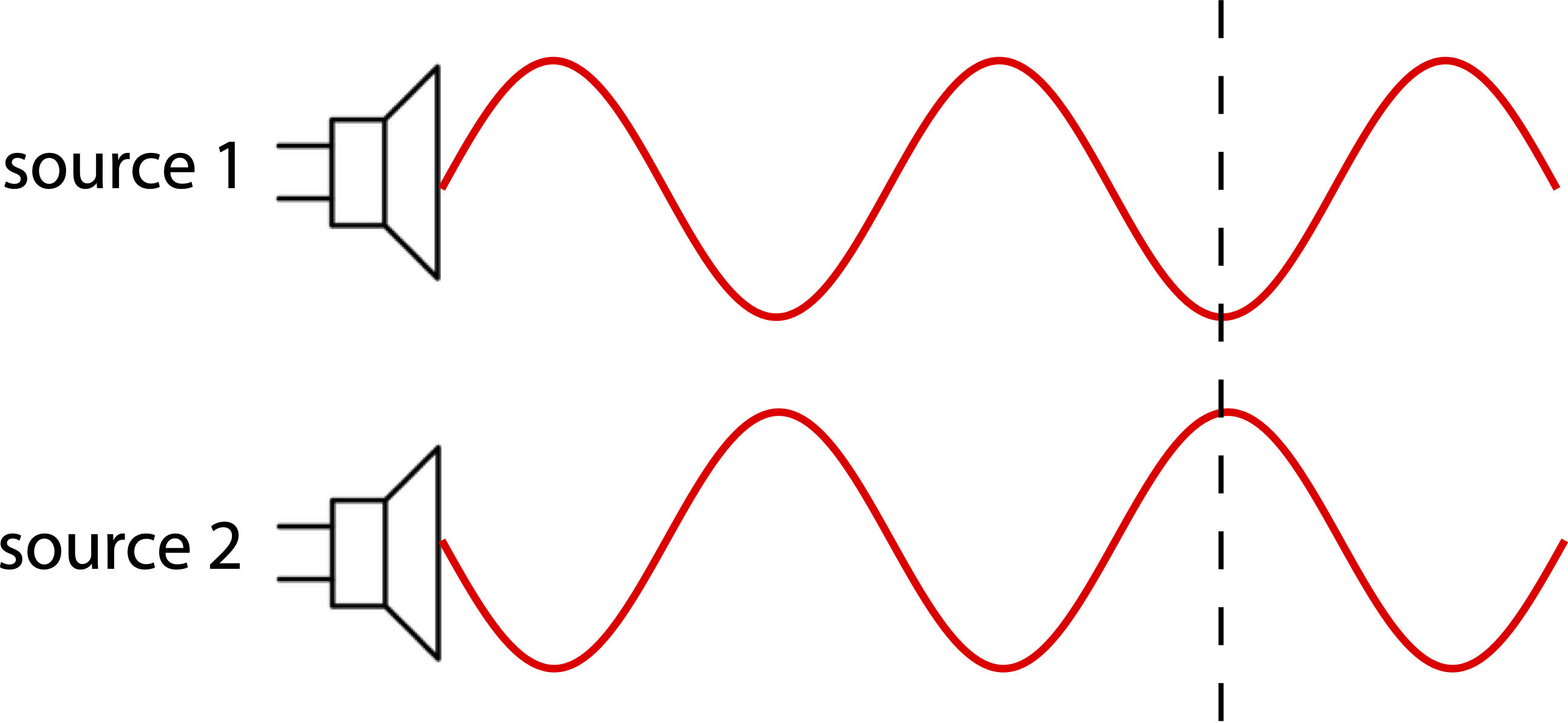
In this case since the two sources are at the same location, \(\Delta x=0\). The difference in their phase constants is \(\pi\). This results in the following expression for the total phase difference:
\[\Delta\Phi = - \dfrac{2 \pi}{\lambda}\cdot 0 + \pi=\pi\]
which confirms destructive interference which is observed in Figure 8.5.4. Note, this scenario could also be interpreted as two sources with equal phase constants being turned on half a period after one another. This would mean that there is a difference in time between the two sources, but as we already discussed, any difference in time can always be interpreted as a difference in a phase constant, such as we treated this problem here.
The figure below shows another example, where the phase difference is caused by difference in position of the two sources. Source 2 is behind source 1 by a distance of one wavelength. The two sources have the same phase constant, since both are producing identical waves in this snapshot. The only difference between the two sources is their relative positions.
Figure 8.5.5: Path Length Difference for Constructive Interference
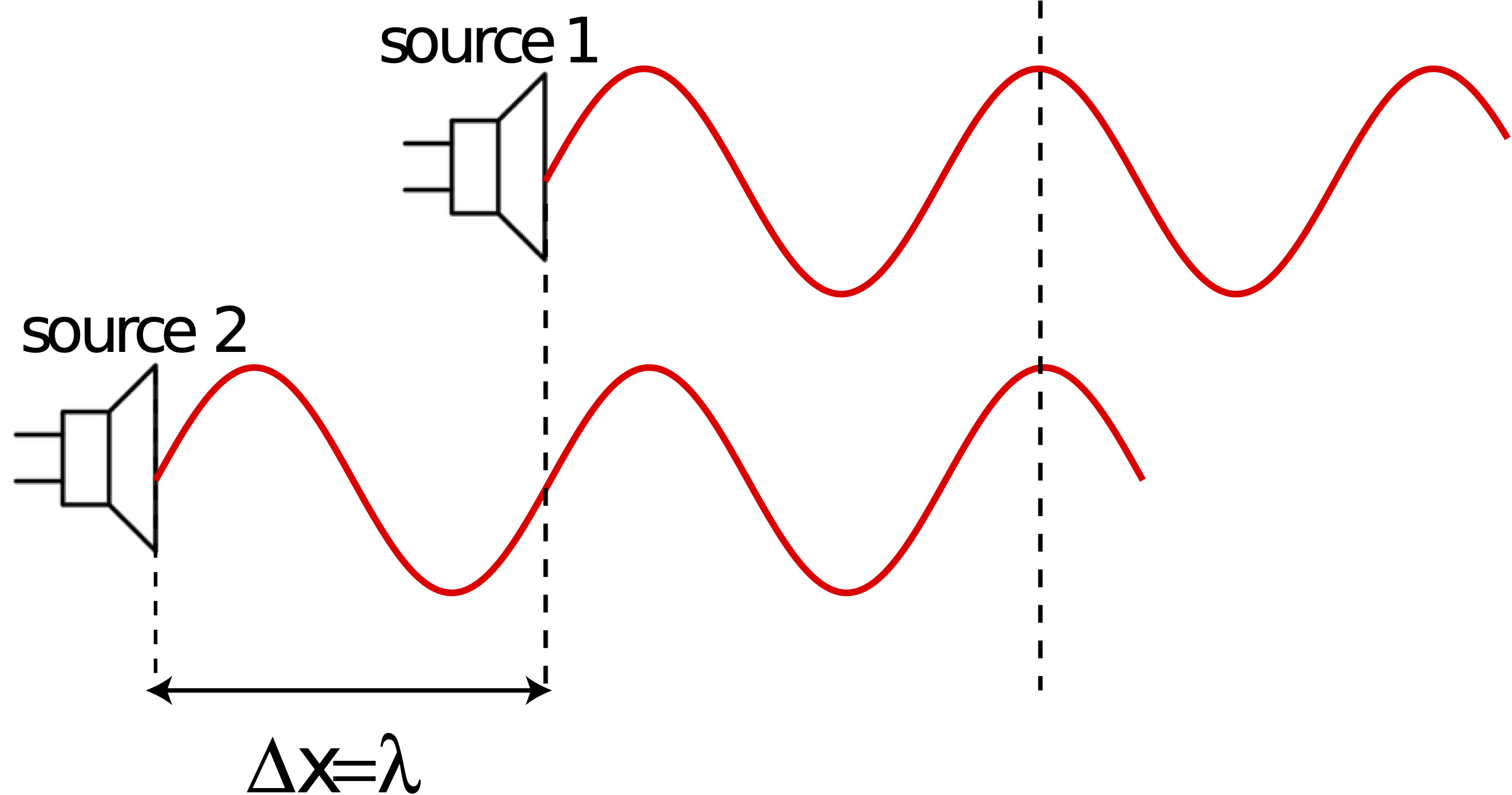
The position in this case matters since although the two speakers are in phase (equal phase constants), the wave from source 2 travels a longer distance to the observer compared to the wave from source 1. The difference between these two positions, \(\Delta x\), is known as the path length difference. In this example, that path length difference is exactly one wavelength, \(\Delta x=x_2-x_1=\lambda\), according to an observer who is standing to the right of both speakers (for example, at the location of the last vertical dashed line). This particular path length difference is identical to the situation if the two speakers were in the same locations. This results in constructive interference as seen above. Mathematically, the total phase difference for the situation in Figure 8.5.5 is written as:
\[\Delta\Phi = -\dfrac{2 \pi}{\lambda}\lambda+0=-2\pi \]
giving the condition for constructive interference. The figure below shows a similar situation, except now source 2 is half a wavelength behind source 1, such that \(\Delta x=x_2-x_1=\lambda/2\). As can be seen in the figure, in this case crests and lining up with troughs, which will resulting cancellation of amplitudes.
Figure 8.5.6: Path Length Difference for Destructive Interference
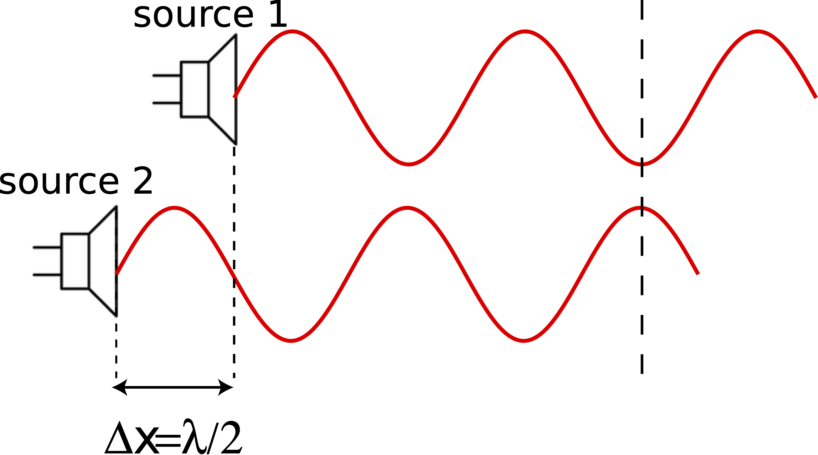
Mathematically, plugging in for the the path length difference we obtain the result for destructive interference:
\[\Delta\Phi = -\dfrac{2 \pi}{\lambda}\dfrac{\lambda}{2}+0=-\pi \]
Notice that the difference is positions stays the same everywhere on the right of the two speakers. Although, we choose to draw the waves only emanating to the right of the speakers, in reality they are being generated in three-dimensions around the speakers. To the left of the two speakers, for example, the value of, \(x_2-x_1\), would be negated since now source 2 is now closer. But if interference is being measured somewhere where the speakers and the observer no longer make a straight line, the same concepts hold for the path length difference. The illustration below shows a general description of path length difference.
Figure 8.5.7: Path Length Difference
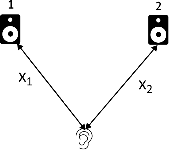
The observer is standing a distance \(x_1\) from speaker 1 and a distance of \(x_2\) from speaker 2. The path length difference is then defined as:
\[\Delta x= x_2-x_1\]
If the interference is being measured locations which are the same distance to each speaker, then the path length difference is zero. Otherwise, it is important to calculate what fraction of the wavelength is the difference in the distance to each source. Note, once you define one particular source as "1" and the other as "2", make sure to be consistent in calculating the total phase difference, such that you are subtracting the phase constant of speaker 1 from the phase constant speaker 2, as well.
The last example shown below depicts a combination of the effect of a difference in both the phase constant and the path length. The two sources shown have a phase constant difference of \(\pi\), and source 2 is half a wavelength behind source 1.
Figure 8.5.8: Path Length Difference and Phase Constant Difference
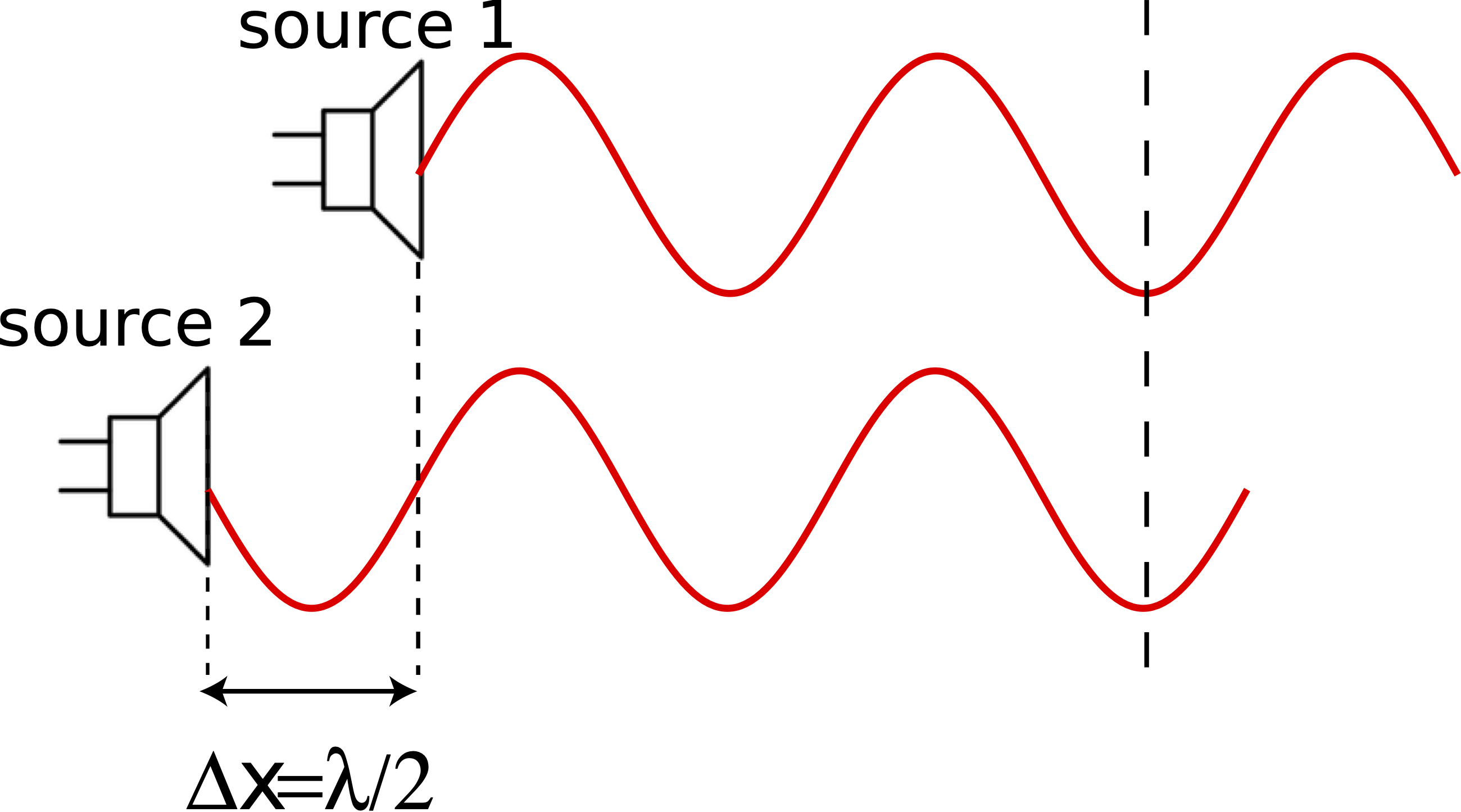
Plugging this scenario into the equation for the total phase difference, we obtain:
\[\Delta\Phi = -\dfrac{2 \pi}{\lambda}\dfrac{\lambda}{2}+\pi=0 \]
which gives the condition for constructive interference, as can be seen in the figure since crests and troughs are lining up from each wave. This example stresses that it is important to consider the combination of both effects. We saw in the example presented in Figure 8.5.4 that a phase difference of half a cycle results in destructive interference. Then we saw from Figure 8.5.6 that a path length difference of half of a wavelength also results in destructive interference. In this example, both of these effects, which individual give rise to destructive interference, when are presents simultaneously result in constructive interference.
Example \(\PageIndex{1}\)
In the diagram below there are three speakers. When turned on all three are emitting a tone with a wavelength of \(2~m\). Alice who is standing at location A hears no sound when only speakers 1 and 2 are turned on. Brendan who is standing at location B hears a loud sound of maximum intensity when only speakers 2 and 3 are turned on.
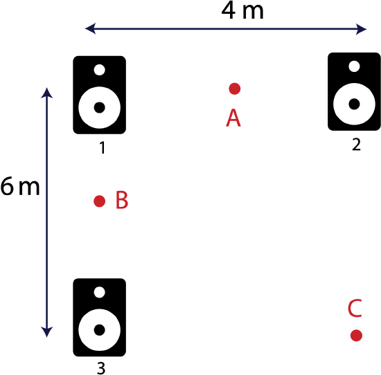
Calculate \(\Delta\Phi\) and determine the type of interference that Crystal standing at location C will hear when:
a) Only speakers 1 and 2 are turned on.
b) Only speakers 1 and 3 are turned on.
c) Only speakers 2 and 3 are turned on.
- Solution
-
First we need to use the provided information to figure out the phase constant differences between the various speakers. When speakers 1 and 2 are turned on, the interference is destructive at location A: \(\Delta\Phi_{12}=2\pi(n+1/2)\). The path length difference is zero, \(\Delta x_{12}=0\), since Alice is equidistant to speakers 1 and 2. This results in the following expression for the fixed phase constant difference between the two speakers, \(\Delta\phi_{12}\):
\[\Delta\Phi_{12}=0+\Delta\phi_{12}=2\pi\Big(n+\dfrac{1}{2}\Big)\nonumber\]
Choosing the \(n=0\) solution for convenience, we obtain the following expression for the phase constant difference between speakers 1 and 2:
\[\Delta\phi_{12}=\pi\nonumber\]
When speakers 2 and 3 are turned on the interference is constructive at location B, \(\Delta\Phi_{23}=2n\pi\), since Brendan hears maximum loudness. The distance from B to speaker 3 is 3 m. To find the distance to speaker 2, we need to use Pythagorean theorem, since point B, speaker 1, and speaker 2 make a right triangle. The distance from B to speaker 2 is the hypotenuse of this triangle:
\[x_2=\sqrt{3^2+4^2}=5~m\nonumber\]
Putting these results together to obtain the difference in the total phase at location B when speakers 2 and 3 are turned on:
\[\Delta\Phi_{23}=-\dfrac{2\pi}{2m}(5-3)+\Delta\phi_{23}=2\pi n\nonumber\]
Simplifying and choosing the \(n=-1\) solution we find:
\[\Delta\phi_{23}=0\nonumber\]
Since the speakers 3 and 2 are in phase, the phase difference between 1 and 2 will be the same as the phase difference between 1 and 3:
\[\Delta\phi_{13}=\pi\nonumber\]
Now, we ready to answer the three questions about inference that Crystal hears when all the possible pairs of speakers are turned on. The distance to speaker 1 from location C is obtained using Pythagorean theorem again:
\[x_1=\sqrt{4^2+6^2}=2\sqrt{13}m\nonumber\]
The distance to speaker 2 is 6 m, \(x_2=6m\), and the distance to speaker 3 is 4 m \(x_2=4m\).
a) When speakers 1 and 2 are turned on the path length difference is, \(x_1-x_2=(2\sqrt{13}-6)\) m. The difference in the total phase is:
\[\Delta\Phi_{12}=-\dfrac{2\pi}{\lambda}\Delta x_{12}+\Delta\phi_{12}=-\dfrac{2\pi}{2m}(2\sqrt{13}-6)m+\pi=-0.211\pi\nonumber\]
The interference is partial and is closer to constructive since the phase difference is closer to zero than to \(\pi\).
b) When speakers 1 and 3 are turned on the path length difference is, \(x_1-x_3=(2\sqrt{13}-4)\) m. The difference in the total phase is:
\[\Delta\Phi_{13}=-\dfrac{2\pi}{\lambda}\Delta x_{13}+\Delta\phi_{13}=-\dfrac{2\pi}{2m}(2\sqrt{13}-4)m+\pi=-2.211\pi\nonumber\]
The total phase difference above is identical to part a) since the two results differ by \(2\pi\), so the interference is the same due to these first two scenarios.The only difference between the two cases is the distance to speaker 2 is 2m longer than the distance to speaker 3. But this does not make a difference when it comes to interference since 2m is exactly one wavelength, so the path length difference is difference by one wavelength in part a). One wavelength is a shift by one cycle, resulting in identical interference.
c) When speakers 2 and 3 are turned on the path length difference is, \(x_2-x_3=6-4=2m\). The difference in the total phase is:
\[\Delta\Phi_{23}=-\dfrac{2\pi}{\lambda}\Delta x_{23}+\Delta\phi_{23}=-\dfrac{2\pi}{2m}(2m)+0=-2\pi\nonumber\]
Thus, the inference in this case is constructive.
Example \(\PageIndex{2}\)
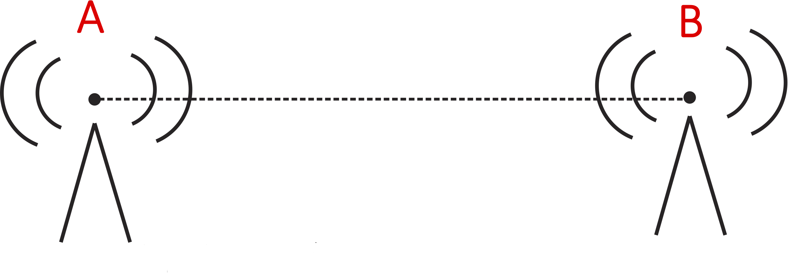
You happen to be lost in a middle of a desert, in between two radio towers which are 15 km apart. Both towers are transmitting radio waves of frequency \(3.75\times 10^4~Hz.\) The radio signals are interfering with your GPS and not allowing you to find your way out. When you are standing along the straight line between the two towers 7 meters away from tower A, you find constructive interference. Instead, you want to find locations of destructive interference, so you can use your navigation system. Find all such positions on the line connecting towers A and B. Express your answer in terms of distance from tower A. Note, radio waves are electromagnetic waves which travel at the speed of light, \(c=3\times 10^8~m/s\). Electromagnetic waves also interfere when they meet in the same location in space, using the same principles as sound waves.
- Solution
-
The goal here is to find all possible path length differences between towers A and B where interference is destructive. The phase constant difference is not given directly, but we are told that the interference is constructive when you are 7 km away from tower A. At this location you are 8 km from tower B, since they are 15 km apart. Therefore, the path length difference is:
\[x_B-x_A=8-7=1km\nonumber\]
We also need to determine the wavelength in order to calculate the total phase differences. The wavelength for these radio waves is:
\[\lambda=\dfrac{c}{f}=\dfrac{3\times 10^8 m/s}{3.75 \times 10^4 Hz}=8000~m=8~km\nonumber\]
Since the interference is constructive at this location, the total phase difference is \(2\pi n\):
\[\Delta\Phi_{BA}=-\dfrac{2\pi}{\lambda}(x_B-x_A)+\phi_B-\phi_A=-\dfrac{2\pi}{8km}(1km)+\phi_B-\phi_A=2\pi n\nonumber\]
Solving for the fixed phase constant difference:
\[\phi_B-\phi_A=2\pi n+\dfrac{\pi}{4}=\dfrac{\pi}{4}\nonumber\]
Note, we chose \(n=0\) solution for convenience.
Now that we know the phase constant difference, let us find all the path length differences between the two towers which will result in destructive interference:
\[\Delta\Phi_{BA}=-\dfrac{2\pi}{8}(x_B-x_A)+\dfrac{\pi}{4}=2\pi\Big(n+\dfrac{1}{2}\Big)\nonumber\]
Solving for path length difference:
\[x_B-x_A=-8n-3\nonumber\]
The equation above has an infinite number of solutions, but we are constrained since your locations needs to be on the line connecting the two towers. The closest possible position to tower A is if you were standing at the location of A, resulting in \(x_A=0\) and \(x_B=15\). The furthest position from tower A is at tower B, \(x_A=15\) and \(x_B=0\). Therefore, the path length difference can only have the following values between the two towers:
\[-15\leq (x_B-x_A)\leq 15\nonumber\]
Thus, we need to find all values of \(n\) which satisfy the above constraint. Starting with small values of \(n\) and increasing them until we no longer satisfy the above equation, we get the following four solutions:
\[\begin{array}{l} n = 0: & x_B-x_A=-3 ~km \\ n = 1: & x_B-x_A=-11~km \\ n=-1: & x_B-x_A=5~km \\ n=-2: & x_B-x_A=13~km \end{array}\nonumber\]
A positive value of \(n\geq 2\) or a negative value \(n\leq -3\) would result in a path length difference outside the allowed range, placing you in either the right or the left of both towers. The path length difference does not give you the exact distance from tower A, \(x_A\). But we can use the fact that the sum f the distances to towers A and B has to be 15 km:
\[x_A+x_B=15~km\nonumber\]
Now we have two equations with two unknowns, so we can solved for \(x_A\) for each of the four solutions above:
\[x_A= 1~km, 5~km, 9~km, \text{and}~13~km\nonumber\]
To check that these values are correct, plug them back into the phase difference equation and check that you get destructive interference.
Wavefront Representation of Interference
We can also use the wavefront representation as another tool of depicting wave interference. Shown in the figure below are two sources generating waves with equal wavelengths, and thus frequencies. The crests (solid lines) and trough (dashed lines) emitted by source A are blue, while those emitted by source B are red. The two sources are near each other such that their wavefronts will meet and overlap in the same location in space.
Figure 8.5.9: Interference between Two Wavefronts
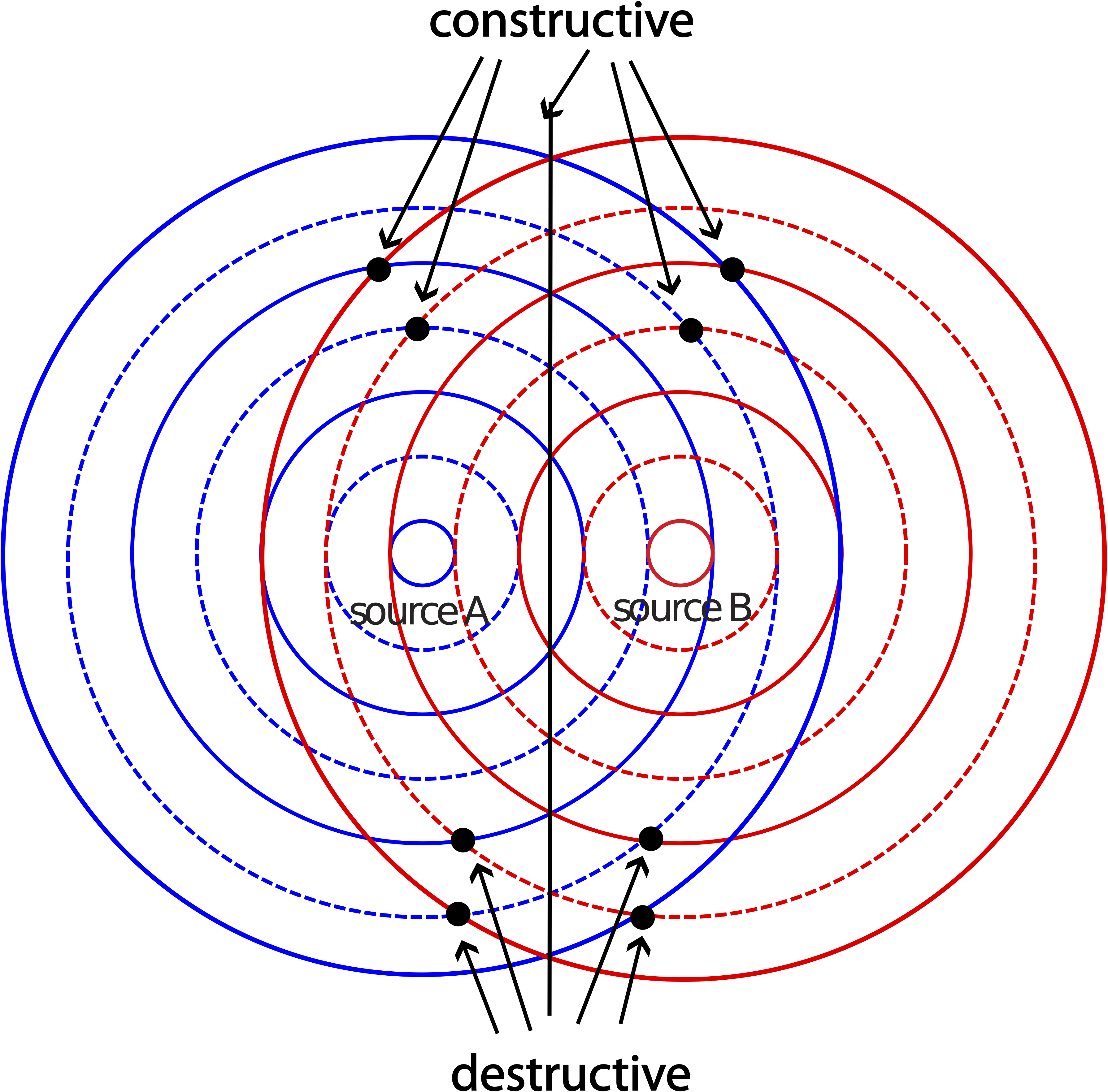
From what we have learned about interference, the two waves will interference constructively when two crests or two troughs overlap. Some of these locations are marked in the figure above. The central line separating the two sources shows a continuous location of constructive interference. How is it possible to conclude that since there are only discrete locations of constructive interference that can be interpreted from the figure due to overlapping crests and troughs? The two sources shown are in phase, since crests and troughs are being being generated at the same time. (On the contrary, if you were to replace all the crests for one of the sources by troughs and all the troughs by crests, that would depict two sources which are half a cycle of of phase.) In addition, the path length difference is zero along the central line since the distances to each source are equal. This implies that the total phase difference along the central line will always be zero, resulting in constructive interference.
Locations of destructive Interference are marked at some of the places where a crest from one source meets a trough from the other source, resulting in cancellation of amplitudes. The picture above is a snapshot at a particular instance of time. At a later time, there will be more wavefronts present and more visible locations of constructive and destructive interference. The wavefront representation does not give us a full picture of interference, since we only have information about crests and troughs at a given instance of time, but it provide a good guide. Unlike the central line which is a highly symmetric situation, it is more difficult to predict all the locations of interference without doing a precise calculation of path length differences.
Example \(\PageIndex{1}\)
Two sources, A and B, are emitting sounds waves. The picture below shows two crests which originated from source A (solid red circles) and two troughs from source B (dashed blue circles). Assume everything is depicted to scale.
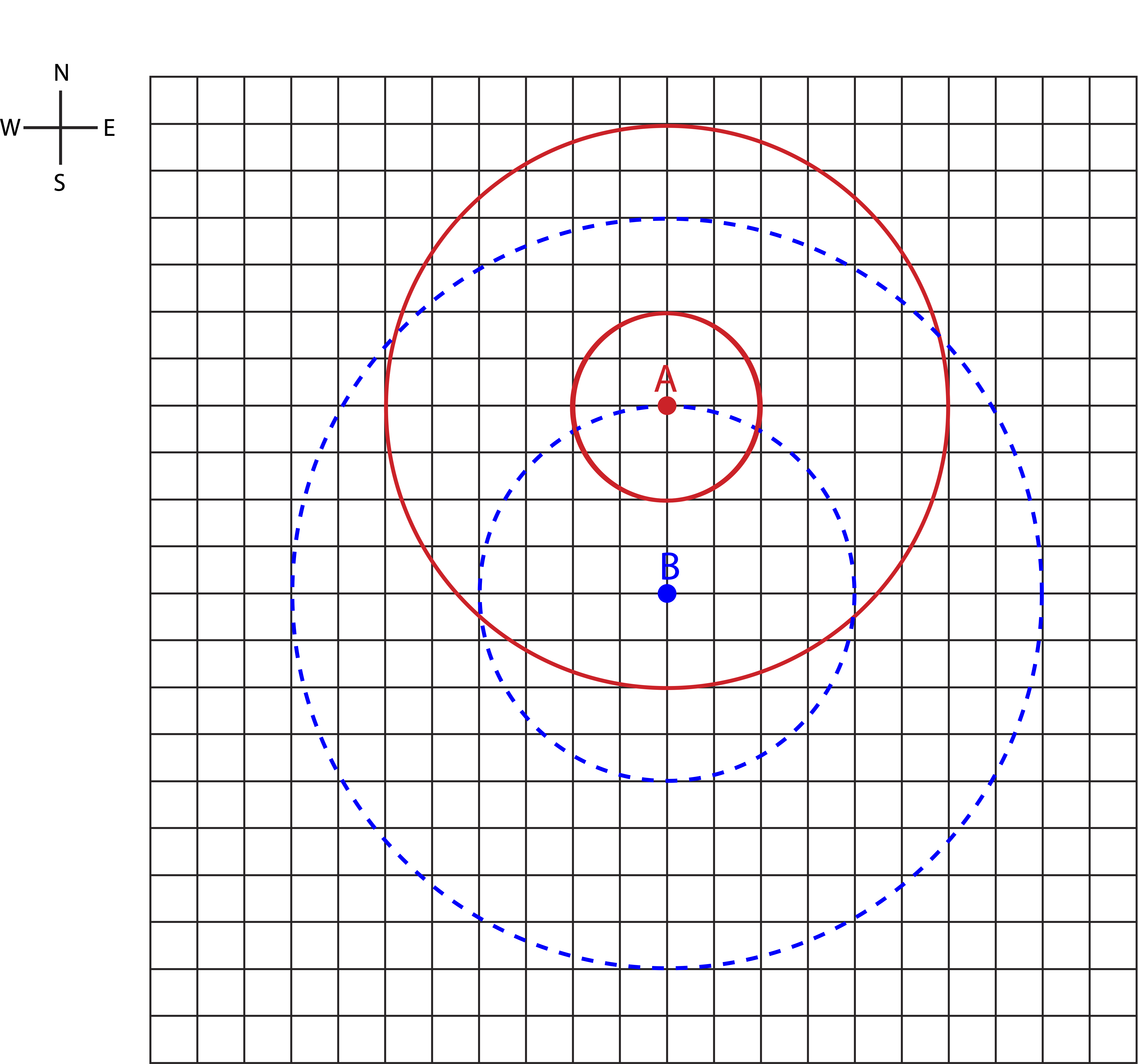
a) Determine the type of interference (constructive, destructive, or partial) directly North of both sources, directly South of the sources, and along the horizontal line midway between the two sources. Explain your reasoning.
b) If you decreased the distance between the same two sources by half, which of the answers from part a) would change and how?
- Solution
-
a) The wavelength is 4 units (distance between 2 crests or two troughs). The distance between the two sources is also 4 units. Thus, the two sources are one wavelength apart. It it not shown in the figure, but there is a trough for source A halfway between the two crests, or a distance of 4 units from source. That's exactly the distance of a trough emitted from source B. Therefore, when source A is emitting a trough, source B is emitting a trough as well, so the two sources are in phase (the difference between their phase constants is zero). On the North and the South of the two sources, the path length difference is just the separation between the sources. Therefore, North or South of the two sources the interference is constructive (path length difference is one wavelength, and the sources are in phase). Along the line midway between the two sources the interference is also constructive (path length difference is zero and the sources are in phase).
b) The new distance between the sources is half a wavelength, so the path length difference for North and South change to \(\lambda/2\), making the interference destructive there. The midpoint still has zero path length difference, so the interference does not change.