
8.7: Double-Slit Interference
- Page ID
- 64620

\( \newcommand{\vecs}[1]{\overset { \scriptstyle \rightharpoonup} {\mathbf{#1}} } \)
\( \newcommand{\vecd}[1]{\overset{-\!-\!\rightharpoonup}{\vphantom{a}\smash {#1}}} \)
\( \newcommand{\dsum}{\displaystyle\sum\limits} \)
\( \newcommand{\dint}{\displaystyle\int\limits} \)
\( \newcommand{\dlim}{\displaystyle\lim\limits} \)
\( \newcommand{\id}{\mathrm{id}}\) \( \newcommand{\Span}{\mathrm{span}}\)
( \newcommand{\kernel}{\mathrm{null}\,}\) \( \newcommand{\range}{\mathrm{range}\,}\)
\( \newcommand{\RealPart}{\mathrm{Re}}\) \( \newcommand{\ImaginaryPart}{\mathrm{Im}}\)
\( \newcommand{\Argument}{\mathrm{Arg}}\) \( \newcommand{\norm}[1]{\| #1 \|}\)
\( \newcommand{\inner}[2]{\langle #1, #2 \rangle}\)
\( \newcommand{\Span}{\mathrm{span}}\)
\( \newcommand{\id}{\mathrm{id}}\)
\( \newcommand{\Span}{\mathrm{span}}\)
\( \newcommand{\kernel}{\mathrm{null}\,}\)
\( \newcommand{\range}{\mathrm{range}\,}\)
\( \newcommand{\RealPart}{\mathrm{Re}}\)
\( \newcommand{\ImaginaryPart}{\mathrm{Im}}\)
\( \newcommand{\Argument}{\mathrm{Arg}}\)
\( \newcommand{\norm}[1]{\| #1 \|}\)
\( \newcommand{\inner}[2]{\langle #1, #2 \rangle}\)
\( \newcommand{\Span}{\mathrm{span}}\) \( \newcommand{\AA}{\unicode[.8,0]{x212B}}\)
\( \newcommand{\vectorA}[1]{\vec{#1}} % arrow\)
\( \newcommand{\vectorAt}[1]{\vec{\text{#1}}} % arrow\)
\( \newcommand{\vectorB}[1]{\overset { \scriptstyle \rightharpoonup} {\mathbf{#1}} } \)
\( \newcommand{\vectorC}[1]{\textbf{#1}} \)
\( \newcommand{\vectorD}[1]{\overrightarrow{#1}} \)
\( \newcommand{\vectorDt}[1]{\overrightarrow{\text{#1}}} \)
\( \newcommand{\vectE}[1]{\overset{-\!-\!\rightharpoonup}{\vphantom{a}\smash{\mathbf {#1}}}} \)
\( \newcommand{\vecs}[1]{\overset { \scriptstyle \rightharpoonup} {\mathbf{#1}} } \)
\(\newcommand{\longvect}{\overrightarrow}\)
\( \newcommand{\vecd}[1]{\overset{-\!-\!\rightharpoonup}{\vphantom{a}\smash {#1}}} \)
\(\newcommand{\avec}{\mathbf a}\) \(\newcommand{\bvec}{\mathbf b}\) \(\newcommand{\cvec}{\mathbf c}\) \(\newcommand{\dvec}{\mathbf d}\) \(\newcommand{\dtil}{\widetilde{\mathbf d}}\) \(\newcommand{\evec}{\mathbf e}\) \(\newcommand{\fvec}{\mathbf f}\) \(\newcommand{\nvec}{\mathbf n}\) \(\newcommand{\pvec}{\mathbf p}\) \(\newcommand{\qvec}{\mathbf q}\) \(\newcommand{\svec}{\mathbf s}\) \(\newcommand{\tvec}{\mathbf t}\) \(\newcommand{\uvec}{\mathbf u}\) \(\newcommand{\vvec}{\mathbf v}\) \(\newcommand{\wvec}{\mathbf w}\) \(\newcommand{\xvec}{\mathbf x}\) \(\newcommand{\yvec}{\mathbf y}\) \(\newcommand{\zvec}{\mathbf z}\) \(\newcommand{\rvec}{\mathbf r}\) \(\newcommand{\mvec}{\mathbf m}\) \(\newcommand{\zerovec}{\mathbf 0}\) \(\newcommand{\onevec}{\mathbf 1}\) \(\newcommand{\real}{\mathbb R}\) \(\newcommand{\twovec}[2]{\left[\begin{array}{r}#1 \\ #2 \end{array}\right]}\) \(\newcommand{\ctwovec}[2]{\left[\begin{array}{c}#1 \\ #2 \end{array}\right]}\) \(\newcommand{\threevec}[3]{\left[\begin{array}{r}#1 \\ #2 \\ #3 \end{array}\right]}\) \(\newcommand{\cthreevec}[3]{\left[\begin{array}{c}#1 \\ #2 \\ #3 \end{array}\right]}\) \(\newcommand{\fourvec}[4]{\left[\begin{array}{r}#1 \\ #2 \\ #3 \\ #4 \end{array}\right]}\) \(\newcommand{\cfourvec}[4]{\left[\begin{array}{c}#1 \\ #2 \\ #3 \\ #4 \end{array}\right]}\) \(\newcommand{\fivevec}[5]{\left[\begin{array}{r}#1 \\ #2 \\ #3 \\ #4 \\ #5 \\ \end{array}\right]}\) \(\newcommand{\cfivevec}[5]{\left[\begin{array}{c}#1 \\ #2 \\ #3 \\ #4 \\ #5 \\ \end{array}\right]}\) \(\newcommand{\mattwo}[4]{\left[\begin{array}{rr}#1 \amp #2 \\ #3 \amp #4 \\ \end{array}\right]}\) \(\newcommand{\laspan}[1]{\text{Span}\{#1\}}\) \(\newcommand{\bcal}{\cal B}\) \(\newcommand{\ccal}{\cal C}\) \(\newcommand{\scal}{\cal S}\) \(\newcommand{\wcal}{\cal W}\) \(\newcommand{\ecal}{\cal E}\) \(\newcommand{\coords}[2]{\left\{#1\right\}_{#2}}\) \(\newcommand{\gray}[1]{\color{gray}{#1}}\) \(\newcommand{\lgray}[1]{\color{lightgray}{#1}}\) \(\newcommand{\rank}{\operatorname{rank}}\) \(\newcommand{\row}{\text{Row}}\) \(\newcommand{\col}{\text{Col}}\) \(\renewcommand{\row}{\text{Row}}\) \(\newcommand{\nul}{\text{Nul}}\) \(\newcommand{\var}{\text{Var}}\) \(\newcommand{\corr}{\text{corr}}\) \(\newcommand{\len}[1]{\left|#1\right|}\) \(\newcommand{\bbar}{\overline{\bvec}}\) \(\newcommand{\bhat}{\widehat{\bvec}}\) \(\newcommand{\bperp}{\bvec^\perp}\) \(\newcommand{\xhat}{\widehat{\xvec}}\) \(\newcommand{\vhat}{\widehat{\vvec}}\) \(\newcommand{\uhat}{\widehat{\uvec}}\) \(\newcommand{\what}{\widehat{\wvec}}\) \(\newcommand{\Sighat}{\widehat{\Sigma}}\) \(\newcommand{\lt}{<}\) \(\newcommand{\gt}{>}\) \(\newcommand{\amp}{&}\) \(\definecolor{fillinmathshade}{gray}{0.9}\)Huygens' Principle
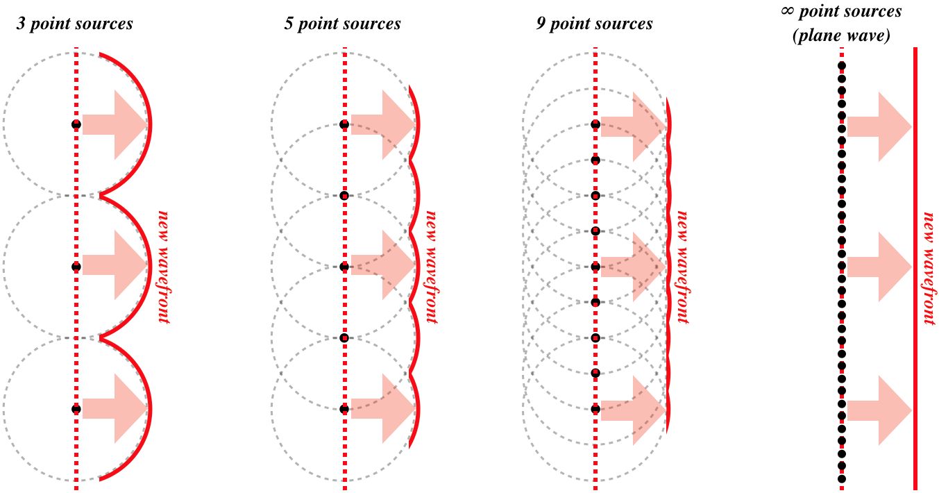
Before diving into the the double-slit phenomena, we introduce a new tool that can be used to explain a lot of wave phenomena, known as the Huygens' Principle. It is named after a Dutch scientist Christiaan Huygens. In 1678 Huygens proposed that each point along a moving wavefront can be represented by a point source of a spherical waves. The wavefronts that are observed are due to the interference of all of these spherical waves.
The figure below demonstrates Huygen's Principle by starting with a simplified picture of just three point sources on the very left of the figure. These three waves will interfere giving rise to the "new wavefront" which is wavelike. As you add more and more wavelets close together along a line, the overlap between the wave becomes more and more regular, until in becomes continuous giving rise to a straight wavefront when we have an "infinite" number of sources on the very right of the figure. Therefore, a plane wave coming from a distant object can be described as a combination of infinite number of point sources each generating an independent wavelet.
Figure 8.7.1: Huygens' Principle
Huygen's Principle is especially useful when explaining what happens to wavefronts when they encounter barriers. In the figure below on the left, a wavefront represented by a superposition of infinite point sources, encounters a barrier. The part of the wavefront that hits the barrier gets either reflected or absorbed by its surface, while the rest of the wavefront propagates forward. However, the wavelet generated by the point source right at the boundary of the barrier will no longer interfere with neighboring point sources below it. Thus, the spherical waves generated from the point sources near the barriers will be retained as shown in the figure. This will result in the wave bending around the barrier as shown in the figure. Recall, the direction of wave propagation is always perpendicular to the wavefront, as described in the ray representation in an earlier section.
Figure 8.7.2: Diffraction
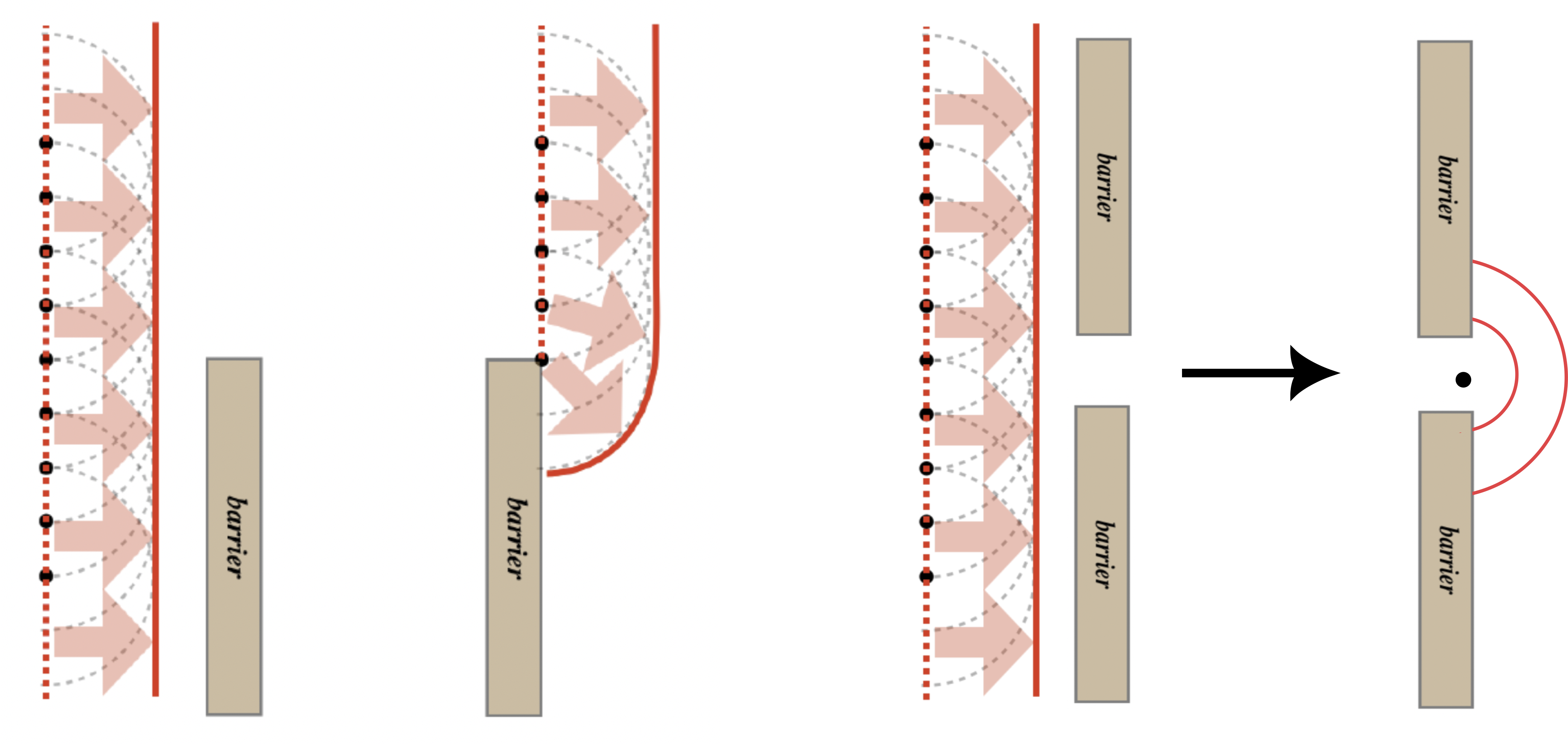
On the right diagram in the figure there are two barriers with a small opening between them. The opening leaves only the small portion of the wavefront that can pass between the barriers. If the opening is small enough, on the order of one wavelength, then there will not be sufficient interference between the neighboring wavelets for the plane wave to continue propagation forward. The wave will bend around the corners of both barriers, resulting in a complete spherical wave propagating onward from the opening. Thus, the opening acts as a new source that generates a spherical wave. This phenomenon is known as diffraction.
We will mostly focus on diffraction of light. Since light typically has very short wavelengths, diffraction of light can be observed only when the opening is extremely small. Diffraction of water and sound waves can be more easier observed since their wavelengths are much longer than that of light, thus the openings do not need to be microscopically small to witness diffraction. You can often observe water waves diffract around boats or peers. A sound can appear to be heard from around a corner or a door opening due to diffraction, even though the original source is much further from the door.
Double-Slit Experiment
The double-slit experiment is a famous experiment which demonstrates light diffraction through two small slits (openings). Since in this experiment there are now two openings through which the incoming wavefronts encounter, there are two nearby light sources that are generated at each slit according to Huygens' Principle. These are two nearby sources interfere and generate an interference pattern. An animation of the double-slit experiment is shown in the figure below.
Figure 8.7.3: Double-Slit Experiment
The animation above depicts the interference between the two light sources using the wavefront representation. The red wavefronts are coming from the lower slit, while the blue ones are coming from the upper slit. Solid wavefronts are crests and dashed ones are troughs. We see that locations of constructive interference are where two crests or two troughs overlap, while destructive interference occurs when a crest from one slit overlaps with a trough from the other. If you were to place a screen on the right side of the two slits, then the locations of constructive inference will appear as bright spots (equivalent to maximum loudness for sound), and locations of destructive interference would appear at dark spots (equivalent to silence when two sound waves cancel). There will be a central bright spot due to constructive interference in the middle between the two slits, followed by alternating bright and dark regions, also known as fringes, on either side of the central bright spot.
You may wonder why we are spending the time analyzing this seemingly particular scenario, but this experiment actually had very important historical significance. The double-slit experiment was first carried out by a British scientist Thomas Young in 1801. As as result it's often referred to as the Young's interference experiment. During that time there was a debate on whether light is a wave or a particle between scientists. Christiaan Huygens was one of the first to mathematically express the "Wave Theory of Light" in 1678. Contradictory to this theory, Isaac Newton claimed that light is made up of tiny particles which he described as corpuscles in his "Corpuscular Theory of Light" in 1675. Young's experiment demonstrated the wave-nature of light, since only waves can exhibit these interference patterns. This settled the debate for the time being, and the Wave Theory of Light became widely accepted. However, a century later this question was revisited once again with the emergence of quantum mechanics, which showed that light has both wave and particle properties.
Let us now analyze mathematically the interference of the light sources emerging from the two slits as in appears on a screen placed to the right of the slits. We will assume that the incoming light is monochromatic (one color), consisting of one frequency and wavelength, unlike white light which is a combination of a mixture of all wavelengths of visible light. In addition we assume that the light is coherent, all the waves generated by the sources are in phase. Most sources of light generate incoherent light with random phases. We need both of these properties to allow to a fixed pattern of interference such that the sources at the slits have the same frequency and phase constant. In modern times, this is typically achieved with lasers which generate monochromatic coherent beams of light.
With coherent light entering the slits, we can assume that the two sources generated at two slits are in phase, \(\Delta\phi_o=0\). We are also using monochromatic source of light, so we do not need to consider waves of difference frequencies interfering, as we did for beats in the previous section. Therefore, the total phase difference for a double-slit setup only depends on the path length difference, \(\Delta x\), which is the difference in the distance from some location on the screen to each slit. The total phase difference is given by:
\[\Delta\Phi=-\dfrac{2\pi}{\lambda}\Delta x=\begin{cases} 2\pi n:~\text{constructive}\\ 2\pi\left(n+\dfrac{1}{2}\right): \text{destructive}\end{cases}~n=0,\pm 1, \pm 2, ...\label{dPhi-slits}\]
The path length difference arises from the rays of light traveling a different distance from each slit to the screen. The figure below will help us visualize the geometry in order to calculate the path length differences for various locations along the screen. The distance from the midpoint between the two slits (the dashed horizontal line in the figure below) to each slit is the same, thus the path length difference is zero, \(\Delta x=0\), resulting in constructive interference for the central bright spot which is labeled n=0 in the figure.
Figure 8.7.4: Geometry of the Double-Slit Experiment
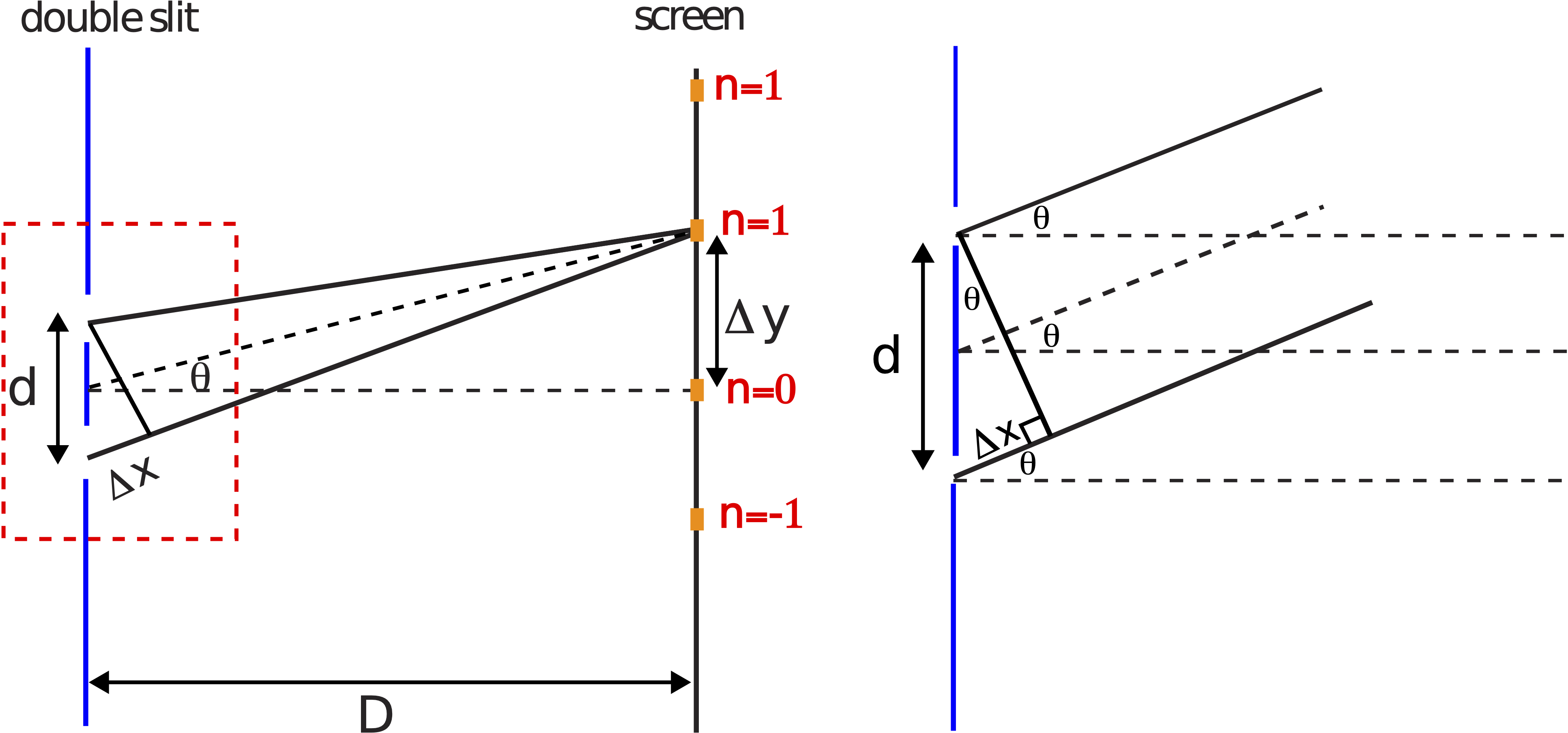
The left side of the figure above illustrates the path length difference to the first bright spot (n=1) above the central one. In this case \(\Delta x\) is not zero, since the ray from the upper slit has a shorter path than the ray from the lower slit to the n=1 location on the screen. The distance marked \(\Delta x\) is the extra distance that the ray from the lower slit needs to travel to the n=1 location.
We want to define the distance \(\Delta x\) in terms of the angle marked \(\theta\), between the horizontal dashed line in between the two slits and the line to the location on the screen where interference is measured. The geometry of this situation can be greatly simplified if we assume the two rays are parallel. This assumption is valid if screen is much farther away from the slits than the slit separation \(D\gg d\), which is the case in a typical double-slit experimental setup. The right diagram in Figure 8.7.4 shows a "zoomed-in" portion of the rays outlined by the dashed rectangle on the left. If the two rays are parallel all three angles with the horizontal labeled \(\theta\) are equivalent. With some geometry using the right triangle in the figure, you can then express the path length difference in term of this angle and the distance between slits:
\[\Delta x=d\sin\theta\]
Plugging the above expression into \(\Delta x\) in Equation \ref{dPhi-slits}, we get the following condition for the bright fringes (constructive interference) and dark spots (destructive interference) on the screen:
\[d\sin\theta=\begin{cases} \lambda n:~\text{constructive}\\ \lambda\left(n+\dfrac{1}{2}\right): \text{destructive}\end{cases}~n=0,\pm 1, \pm 2, ...\label{dsin}\]
The minus sign in Equation \ref{dPhi-slits} can be absorbed on the right-hand side of the equation, since n is either a positive or a negative interger. The number of bright fringes that appear on the screen has a limit, since the quantity "\(\sin\theta\)" cannot exceed one. When \(\sin\theta=1\), the angle \(\theta\) is \(90^{\circ}\) which means the ray travels parallel to the slits and will never reach the screen. In other words, the number of fringes is determined by the following condition, \(n<d/\lambda\). Since n is an integer, if \(d\leq\lambda\), there will only the the one central bright spot. When \(d/\lambda\) is a non-integer, then you would need to round down \(d/\lambda\) to determine the number of possible n's.
We can also express the distance between two neighboring bright spots, marked \(\Delta y\) in Figure 8.7.4, in terms of the angle \(\theta\) and the distance to the screen \(D\):
\[\tan\theta = \dfrac{\Delta y}{D}\label{tan}\]
You can then solve the above for \(\theta\) and plug it back into the \(\theta\) that appears in Equation \ref{dsin} in order to have a relationship between all the distances: slit separation, \(d\), distance to screen, \(D\), and distance between two neighboring bright spots, \(\Delta y\). However, the resulting equation is cumbersome to work with, since you would need to take the sine of an inverse tangent function. But we can use another useful approximation to greatly simplify the equation. Since we are assuming that \(D\gg d\), that implies that the angle is very small, \(\theta \ll 1\), which results in the following approximation for both the sine and tangent functions:
\[\sin\theta\backsimeq\theta; \tan\theta\backsimeq\theta;~\text{when}~\theta \ll 1 \]
Using this approximation in Equation \ref{tan} we get \(\theta\sim\Delta y/D\). Applying the approximation again in Equation \ref{dsin} to solve for the angle to the n=1 bright spot we get \(\theta \sim \lambda/d\). Finally, setting the two approximations equal to each other we can solve for the separation \(\Delta y\) between two neighboring bright spots in terms of slit seperation, distance to the screen, and the wavelength of light:
\[\Delta y=\dfrac{D\lambda}{d}\label{dy}\]
The distance from the central bright fringe to the first dark spot will be half the distance calculated from Equation \ref{dy}, since the dark spot is exactly halfway between two bright fringes. You can also get this result directly by using the destructive Interference condition from Equation \ref{dsin}. The distance from the central fringe to the second bright spots (\(n=\pm 2\)) is double the distance in Equation \ref{dy}, and so on. Of course, you need to consider the limit of the number of bright spots discussed above and explored further in the example below.
Example \(\PageIndex{2}\)
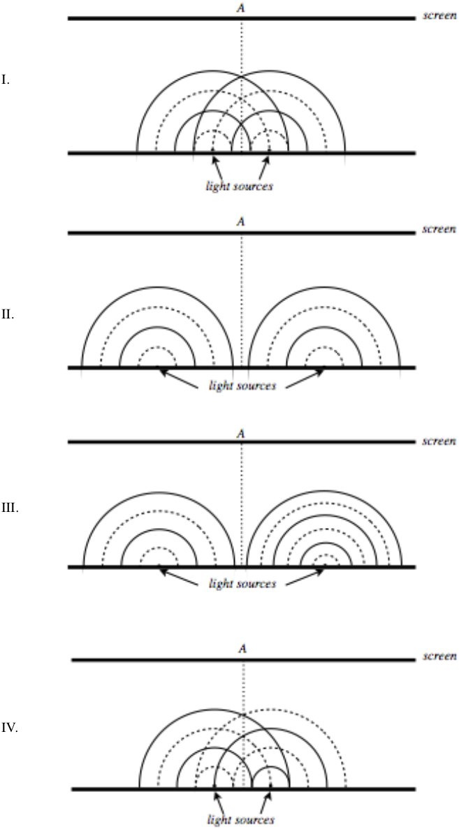
Below are four depictions of two point sources of light (not necessarily caused by two slits), using the wavefront representation. These depictions are snapshots, meaning they are frozen at an instant in time, but the questions below pertain to what happens in real time. Solid lines represent crests, and the dotted lines troughs. For each case, determine the following, and provide explanations:
a) Will these sources create a fixed interference pattern on the distant screen?
b) If there is an interference pattern, what will appear at the point A on the screen, which is directly across from the midway point between the two sources? That is, will it be a bright fringe, a dark fringe, or something in-between?
c) If there is an interference pattern, how many bright fringes will appear on the screen?
- Solution
-
I.
a) Yes. The sources have the same wavelength (and therefore the same frequency), which means that their interference pattern will not have a time-dependent element to them (i.e. they will not provide the light equivalent of “beats”).
b) Bright fringe. The two waves start in phase, and travel equal distances from the sources to get to the center line, so they end up in phase, resulting in constructive interference.
c) One can see by drawing lines through the crossings of crests & troughs that only 3 such lines will strike the screen (parallel to the screen crests match with troughs, so those will not give bright fringes):
We can do this mathematically by noting that these waves start in phase, which means this is equivalent using \(d\sin\theta =m\lambda\) for bright fringes, and by noting from the diagram that the two slits are separated by a distance of \(1.5\lambda\). The fact that \(\sin\theta\) can never be greater than 1 puts a limit on \(m\). This is an integer that can’t be greater than 1.5, so its maximum value is 1, leaving us with 3 bright fringes.
II.
a) Yes. The same reasons as given above for (I.a) apply.
b) Bright fringe. Same reasoning as II.b
c) Now it is not possible (or at least exceedingly difficult) to draw in the lines that lead to constructive interference, so the mathematical method is the only practical approach. This time the slit separation d is clearly more than \(4\lambda\) and less than \(5\lambda\). This means that the highest integer value of \(m\) is 4. With 4 bright fringes on each side of the central bright fringe, the total number is 9.
III.
a) No! These two waves have different wavelengths, and therefore different frequencies, which means that when they interfere, the resulting wave’s amplitude (and therefore the brightness) will be time-dependent.
b) N/A
c) N/A
IV.
a) Yes. Back to equal wavelengths.
b) Dark fringe. These waves start out-of-phase by \(\pi\) radians, so when they travel equal distances, they remain out-of-phase.
c) We can once again draw the lines that follow the paths of constructive interference:
The light sources are separated by \(1.5\lambda\) as they were once before, but now the condition for constructive interference is different, to make up for the starting phase difference. It is now: \(d \sin\theta = \left(m + 1/2\right)\lambda\). We see that there are now two bright spots associated with \(m = 0\), and although there is a solution for \(m = 1,\) it gives \(\theta = \frac{\pi}{2}\), which means the light never reaches the screen, so the number of bright spots on the screen is 2.
Example \(\PageIndex{3}\)
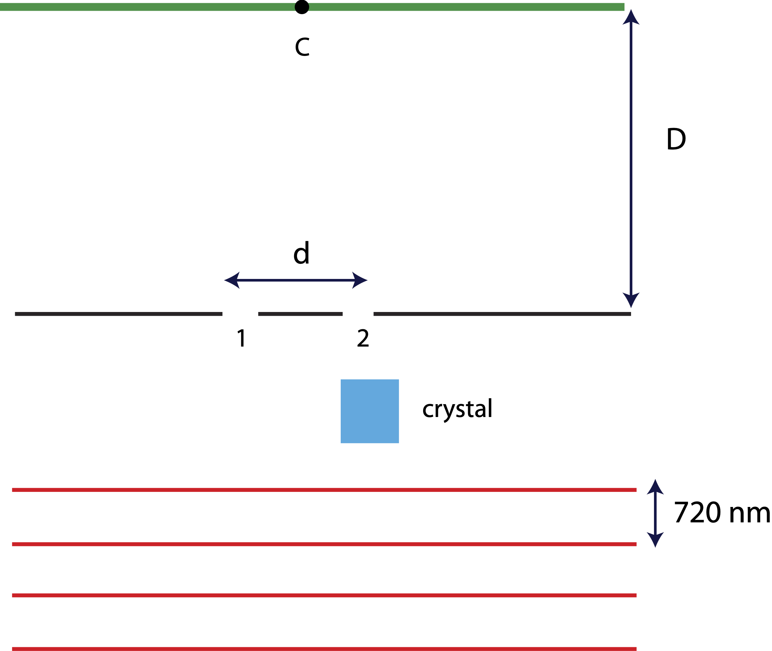
In a double-slit experiment a red-light laser points toward a double-slit with separation \(d\). The distance between two crests of the plane wave generated by the laser is 720 nm. A crystal is placed in front of slit 2 (as shown in the diagram), such that a wavefront arrives at slit 2 exactly \(3\times 10^{-16} s\) after arriving at slit 1. The interference pattern is measure on a screen which is a distance \(D\) from the double-slit. Location C on the screen marks the midpoint between the two slits.
Find the two shortest path length differences which will result in constructive interference on the screen. Determine the location of each of these two bright spots on the screen: at point C, to the right of point C, or to the left of point C?
- Solution
-
Since light travels slower inside the crystal, the wavefronts will be no longer reach the two slits at the same time. This will result in a phase constant difference between the two slits. In order to determine \(\Delta\phi_o\), we need to determine by what fraction of a period does the crystal delay the wavefront.
The distance between two neighboring wavefronts irepresents the wavelength, \(\lambda=720nm=7.2\times 10^{-7} m.\) The period of the red laser is then:
\[T=\dfrac{\lambda}{c}=\dfrac{7.2\times 10^{-7} m}{3\times 10^8 m/s}=2.4\times 10^{-15} s\nonumber\]
Thus, the crystal delays the wavefront by the following fraction of one period:
\[\dfrac{t}{T}=\dfrac{3\times 10^{-16} s}{2.4\times 10^{-15} s}=\dfrac{1}{8}\nonumber\]
In terms of phase, 1/8 of the cycle delay implies that the wave at slit 1 is \(2\pi/8\) ahead of the wave at slit 2, \(\phi_1-\phi_2=\pi/4.\) Solving for the total phase difference which gives constructive interference we get:
\[\Delta\Phi=-\dfrac{2\pi}{\lambda}(x_1-x_2)+\dfrac{\pi}{4}=2\pi n\nonumber\]
Note, for consistency it is important to definte \(\Delta x=x_1-x_2\), since the phase difference is defined at \(\phi_1-\phi_2\).
The shortest path length difference, \(x_1-x_2\), corresponds to n=0:
\[x_1-x_2=\dfrac{\lambda}{8}=\dfrac{720 nm}{8}=90 nm\nonumber\]
Since the sign of \(x_1-x_2\) is positive, the path from \(x_1\) is longer than the path from \(x_2\), implying that this bright spot is to the right of C.
The second shortest \(x_1-x_2\) corresponds to n=1:
\[-\dfrac{2\pi}{\lambda}(x_1-x_2)+\dfrac{\pi}{4}=2\pi\nonumber\]
Solving for \(x_1-x_2\) we obtain:
\[x_1-x_2=-\dfrac{7}{8}\lambda=-\dfrac{7}{8}\times 720 nm=-630 nm\nonumber\]
Since the sign of \(x_1-x_2\) is negative, the path from \(x_2\) is longer than the path from \(x_1\), implying that this bright spot is to the left of C.