
7.6: Static Equilibirium
- Page ID
- 53356

\( \newcommand{\vecs}[1]{\overset { \scriptstyle \rightharpoonup} {\mathbf{#1}} } \)
\( \newcommand{\vecd}[1]{\overset{-\!-\!\rightharpoonup}{\vphantom{a}\smash {#1}}} \)
\( \newcommand{\dsum}{\displaystyle\sum\limits} \)
\( \newcommand{\dint}{\displaystyle\int\limits} \)
\( \newcommand{\dlim}{\displaystyle\lim\limits} \)
\( \newcommand{\id}{\mathrm{id}}\) \( \newcommand{\Span}{\mathrm{span}}\)
( \newcommand{\kernel}{\mathrm{null}\,}\) \( \newcommand{\range}{\mathrm{range}\,}\)
\( \newcommand{\RealPart}{\mathrm{Re}}\) \( \newcommand{\ImaginaryPart}{\mathrm{Im}}\)
\( \newcommand{\Argument}{\mathrm{Arg}}\) \( \newcommand{\norm}[1]{\| #1 \|}\)
\( \newcommand{\inner}[2]{\langle #1, #2 \rangle}\)
\( \newcommand{\Span}{\mathrm{span}}\)
\( \newcommand{\id}{\mathrm{id}}\)
\( \newcommand{\Span}{\mathrm{span}}\)
\( \newcommand{\kernel}{\mathrm{null}\,}\)
\( \newcommand{\range}{\mathrm{range}\,}\)
\( \newcommand{\RealPart}{\mathrm{Re}}\)
\( \newcommand{\ImaginaryPart}{\mathrm{Im}}\)
\( \newcommand{\Argument}{\mathrm{Arg}}\)
\( \newcommand{\norm}[1]{\| #1 \|}\)
\( \newcommand{\inner}[2]{\langle #1, #2 \rangle}\)
\( \newcommand{\Span}{\mathrm{span}}\) \( \newcommand{\AA}{\unicode[.8,0]{x212B}}\)
\( \newcommand{\vectorA}[1]{\vec{#1}} % arrow\)
\( \newcommand{\vectorAt}[1]{\vec{\text{#1}}} % arrow\)
\( \newcommand{\vectorB}[1]{\overset { \scriptstyle \rightharpoonup} {\mathbf{#1}} } \)
\( \newcommand{\vectorC}[1]{\textbf{#1}} \)
\( \newcommand{\vectorD}[1]{\overrightarrow{#1}} \)
\( \newcommand{\vectorDt}[1]{\overrightarrow{\text{#1}}} \)
\( \newcommand{\vectE}[1]{\overset{-\!-\!\rightharpoonup}{\vphantom{a}\smash{\mathbf {#1}}}} \)
\( \newcommand{\vecs}[1]{\overset { \scriptstyle \rightharpoonup} {\mathbf{#1}} } \)
\(\newcommand{\longvect}{\overrightarrow}\)
\( \newcommand{\vecd}[1]{\overset{-\!-\!\rightharpoonup}{\vphantom{a}\smash {#1}}} \)
\(\newcommand{\avec}{\mathbf a}\) \(\newcommand{\bvec}{\mathbf b}\) \(\newcommand{\cvec}{\mathbf c}\) \(\newcommand{\dvec}{\mathbf d}\) \(\newcommand{\dtil}{\widetilde{\mathbf d}}\) \(\newcommand{\evec}{\mathbf e}\) \(\newcommand{\fvec}{\mathbf f}\) \(\newcommand{\nvec}{\mathbf n}\) \(\newcommand{\pvec}{\mathbf p}\) \(\newcommand{\qvec}{\mathbf q}\) \(\newcommand{\svec}{\mathbf s}\) \(\newcommand{\tvec}{\mathbf t}\) \(\newcommand{\uvec}{\mathbf u}\) \(\newcommand{\vvec}{\mathbf v}\) \(\newcommand{\wvec}{\mathbf w}\) \(\newcommand{\xvec}{\mathbf x}\) \(\newcommand{\yvec}{\mathbf y}\) \(\newcommand{\zvec}{\mathbf z}\) \(\newcommand{\rvec}{\mathbf r}\) \(\newcommand{\mvec}{\mathbf m}\) \(\newcommand{\zerovec}{\mathbf 0}\) \(\newcommand{\onevec}{\mathbf 1}\) \(\newcommand{\real}{\mathbb R}\) \(\newcommand{\twovec}[2]{\left[\begin{array}{r}#1 \\ #2 \end{array}\right]}\) \(\newcommand{\ctwovec}[2]{\left[\begin{array}{c}#1 \\ #2 \end{array}\right]}\) \(\newcommand{\threevec}[3]{\left[\begin{array}{r}#1 \\ #2 \\ #3 \end{array}\right]}\) \(\newcommand{\cthreevec}[3]{\left[\begin{array}{c}#1 \\ #2 \\ #3 \end{array}\right]}\) \(\newcommand{\fourvec}[4]{\left[\begin{array}{r}#1 \\ #2 \\ #3 \\ #4 \end{array}\right]}\) \(\newcommand{\cfourvec}[4]{\left[\begin{array}{c}#1 \\ #2 \\ #3 \\ #4 \end{array}\right]}\) \(\newcommand{\fivevec}[5]{\left[\begin{array}{r}#1 \\ #2 \\ #3 \\ #4 \\ #5 \\ \end{array}\right]}\) \(\newcommand{\cfivevec}[5]{\left[\begin{array}{c}#1 \\ #2 \\ #3 \\ #4 \\ #5 \\ \end{array}\right]}\) \(\newcommand{\mattwo}[4]{\left[\begin{array}{rr}#1 \amp #2 \\ #3 \amp #4 \\ \end{array}\right]}\) \(\newcommand{\laspan}[1]{\text{Span}\{#1\}}\) \(\newcommand{\bcal}{\cal B}\) \(\newcommand{\ccal}{\cal C}\) \(\newcommand{\scal}{\cal S}\) \(\newcommand{\wcal}{\cal W}\) \(\newcommand{\ecal}{\cal E}\) \(\newcommand{\coords}[2]{\left\{#1\right\}_{#2}}\) \(\newcommand{\gray}[1]{\color{gray}{#1}}\) \(\newcommand{\lgray}[1]{\color{lightgray}{#1}}\) \(\newcommand{\rank}{\operatorname{rank}}\) \(\newcommand{\row}{\text{Row}}\) \(\newcommand{\col}{\text{Col}}\) \(\renewcommand{\row}{\text{Row}}\) \(\newcommand{\nul}{\text{Nul}}\) \(\newcommand{\var}{\text{Var}}\) \(\newcommand{\corr}{\text{corr}}\) \(\newcommand{\len}[1]{\left|#1\right|}\) \(\newcommand{\bbar}{\overline{\bvec}}\) \(\newcommand{\bhat}{\widehat{\bvec}}\) \(\newcommand{\bperp}{\bvec^\perp}\) \(\newcommand{\xhat}{\widehat{\xvec}}\) \(\newcommand{\vhat}{\widehat{\vvec}}\) \(\newcommand{\uhat}{\widehat{\uvec}}\) \(\newcommand{\what}{\widehat{\wvec}}\) \(\newcommand{\Sighat}{\widehat{\Sigma}}\) \(\newcommand{\lt}{<}\) \(\newcommand{\gt}{>}\) \(\newcommand{\amp}{&}\) \(\definecolor{fillinmathshade}{gray}{0.9}\)Net Force and Torque
Although torque is derived from force, the two concepts are fundamentally different. Forces cause changes in linear motion, while torques cause changes in angular motion. It is possible for forces to cause a net force but no net torque, as it is possible for forces to create a net torque but no net force. Figure 7.6.1 demonstrates a few scenarios using two forces with equal magnitude but varying directions, that result in different combinations of net force and torque.
Figure 7.6.1: Net force and torque
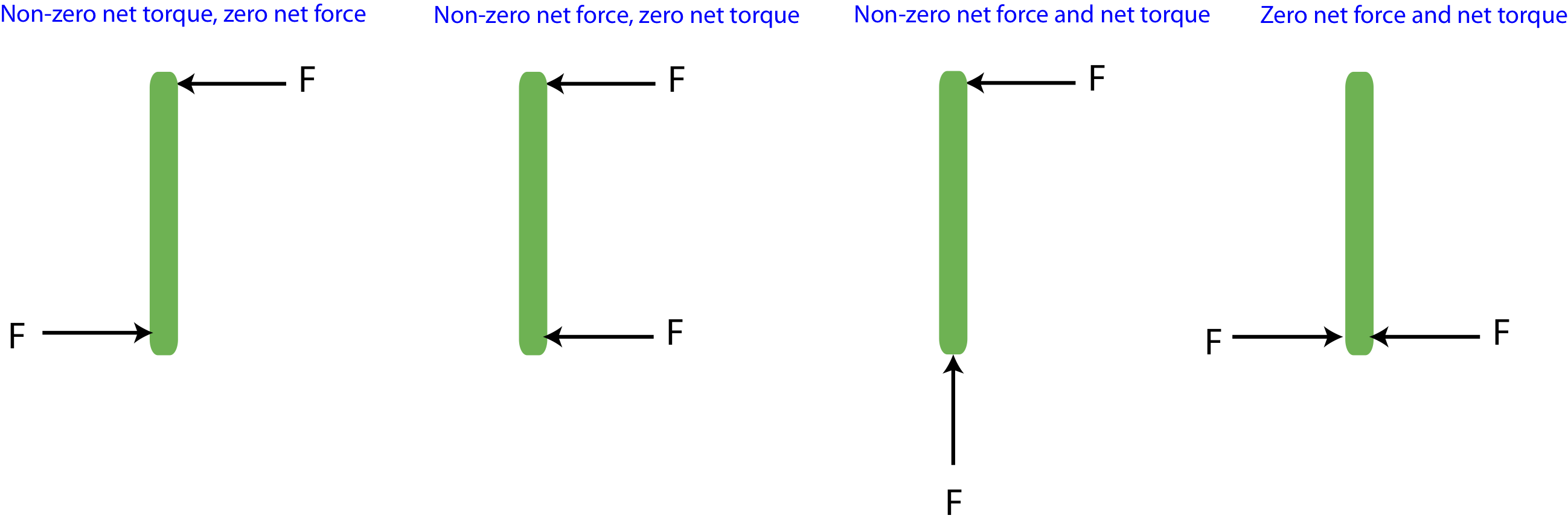
We assume that the bar in the figure is initially stationary, its mass is uniform, and it will rotate about its center. In the first scenario from the left, measuring torque relative to the center, both forces result in a counterclockwise rotation, so the bar will experience angular acceleration since the torques do not cancel. But the forces are equal and opposite, the net force is zero implying that the center of the mass of the bar will remain stationary at the same location. In the second scenario from the left, the two force result in torques of equal magnitude but opposite direction, the upper force result in torque pointing out of the page, while the lower one give a torque pointing into the page, so the two torques will cancel. The net force is to the left since the two forces add in this case, thus the bar will (linearly) accelerate to the left without any rotations. In the third scenario from the left, the lower force does not result in a torque, since it's parallel to the position vector of the force. The upper force will cause a counterclockwise rotation, so there is a net torque pointing out of the page. The forces do not cancel either, and the combination points in northwest direction. Thus, the bar will acceleration linearly in the northwest direction and will rotate counterclockwise with angular acceleration pointing out of the page. In the the last scenario from the last, the forces are again equal and opposite, so the net force is zero. Relative to the center, these forces also result in equal and opposite torques, so the net torque is also zero. This, this bar will remain stationary, neither translating or rotating.
It is often of interest to find situations when that all the forces that act on a system result in zero net force and zero net torque. This ensures that even under the influence of the forces, if the system is initially stationary, it will remain in static equilibrium, meaning that it will not move translationally and will not rotate. The conditions that describe a system in static equilibrium are:
\[\vec\tau_{net}=\sum\vec\tau=0\nonumber\]
\[\vec F_{net}=\sum\vec F=0\nonumber\]
Often you are faced with a problem where you are trying to determine some unknown forces with the assumption that the system is in static equilibrium. For example, you want to hang a heavy object using several ropes at various locations and angles, and you want to make sure the the ropes you use will be able to withstand the type of forces that will be present when the object is hanging in one place. You might find that adjusting the location of the ropes will still result in static equilibrium but will decrease the tension the ropes will feel. Below is a general outline for standard static equilibrium problems, followed by several examples.
Static Equilibrium Problems
Problem-Solving Strategies:
- Isolate and define the physical system which is in static equilibrium.
- Establish a pivot point from which you will measure all distances. Note, a pivot point does not have to be a physical pivot or even on the object you are trying to analyze. If there is a physical pivot present such as a hinge, then a good choice of pivot is at a location of an unknown force. Then the force at the chosen pivot is eliminated in the torque balancing calculation. For a system in static equilibrium, the net torque is zero about any chosen pivot point.
- Draw an extended force diagram on the system, labeling all the forces at the locations where they act and the relevant distances (using position vector or moment arm) from the pivot to each force.
- Determine if any of the forces result in zero torque.
- Using the right hand rule to determine the direction of each torque.
- Since not all forces contribute to torque, it is typically best to start with balancing torques since you can eliminate one of the unknown forces to solve for the second unknown force. Balance torques using the chosen pivot. Instead of choosing a sign convention, you can just equate the sum over torques in one direction to the sum in the opposite direction. For example, the sum of all torques that cause clockwise (CW) rotations is equal to the sum of all torques that cause counterclockwise (CCW) rotations:
\[\sum\tau_{\small{CW}}=\sum\tau_{\small{CCW}}\]
-
Calculate the remaining unknown force by balancing forces by component:
\[\sum F_{net,x}=0\]
\[\sum F_{net,y}=0\]
-
Calculate the magnitude and direction of the unknown forces.
Example \(\PageIndex{1}\)
A child is hanging on a bar attached by two ropes. The rope on the left makes 30° with the horizontal, as shown. The girl weighs 200N and is hanging 1.5 m from the left end of the bar. The bar is uniform, 1.8 m long, and weighs 60N. (Angles and lengths may not be drawn to scale.)
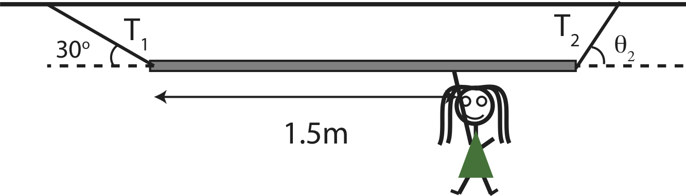
a) Find the tensions in the two ropes, \(T_1\) and \(T_2\), and the angle, \(\theta_2\), that the right rope makes with the horizontal.
b) If the length of the bar was longer while its weight stayed the same, and the girl was still hanging a distance of 5/6 of the bar from the left edge, would the tensions in the ropes increase, decrease, or stay the same?
- Solution
-
a) Choose the location of the right rope as the pivot point, since both the magnitude and direction \(T_2\) is unknown and only the magnitude of \(T_1\) is unknown. The distance to the girl from the pivot is 1.8-1.5=0.3 m. Since the bar is uniform, the center of mass is at L/2=0.9m. The extended force diagram is shown below.
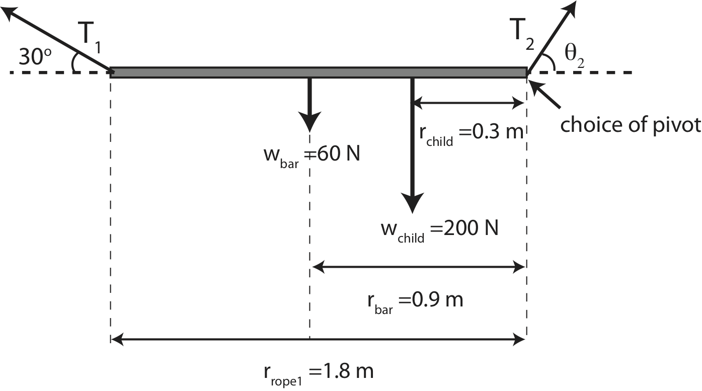
Relative to the chosen pivot point, the weight of the bar and girl will result in counterclockwise rotations, while the tension of rope 1 gives a clockwise rotation. Balancing torques we get:
\[\tau_1=\tau_{\textrm{bar}}+\tau{_\textrm{child}}\nonumber\]
\[r_{\textrm{rope 1}}T_1\sin 30^{\circ}=r_{\textrm{bar}}w_{\textrm{bar}}+r_{\textrm{child}}w_{\textrm{child}}\nonumber\]
Solving for tension we get:
\[T_1=\frac{r_{\textrm{bar}}w_{\textrm{bar}}+r_{\textrm{child}}w_{\textrm{child}}}{r_{\textrm{rope 1}}\sin 30^{\circ}}\nonumber\]
\[T_1=\frac{(0.9m)(60N)+(0.3m)(200N)}{(1.8m)(\sin 30^{\circ})}=126.7~\textrm{N}\nonumber\]
Now we can solve for the components of \(T_2\) by balancing forces. The x-components are:
\[T_{2,x}-T_{1,x}=0\nonumber\]
\[T_{2,x}=T_{1,x}=126.7\cos 30^{\circ}=109.7~\textrm{N}\nonumber\]
The y-components are:
\[T_{2,y}+T_{1,y}-w_{\textrm{bar}}-w_{\textrm{child}}=0\nonumber\]
\[T_{2,y}=w_{\textrm{bar}}+w_{\textrm{child}}-T_{1,y}=200+60-126.7\sin 30^{\circ}=196.7~\textrm{N}\nonumber\]
The magnitude of \(T_2\) is:
\[T_2=\sqrt{109.7^2+196.7^2}=225.2~\textrm{N}\nonumber\]
The angle is:
\[\theta=\arctan\Big(\frac{196.7}{109.7}\Big)=60.9^{\circ}\nonumber\]
pointing in the northeast direction.
b) When balancing torques in this problem, the tensions don’t depend on the total length of the system, but rather where all the forces act relative to each other which is kept the same here. Thus, the answer doesn’t depend on L, and the tensions are the same. And "balancing forces equations” do not depend on the length of the bar either.
Example \(\PageIndex{2}\)
Shown here is a boom of a crane supporting a 50 kg weight with a cable. The boom has a uniform mass of 150 kg and makes a 50° angle with the horizontal.
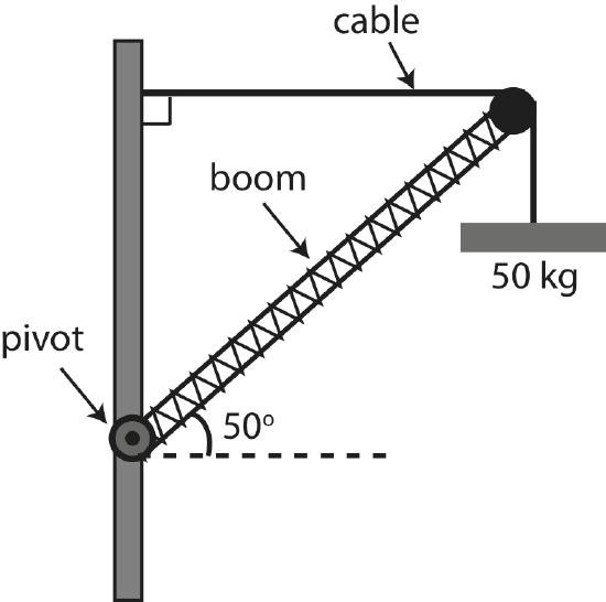
a) Draw an extended force diagram on the boom. Mark all the forces and relevant distances. You may leave forces and distances in terms of variables.
b) Find the magnitude of the tension of the supporting cable (marked on diagram).
c) Calculate the force exerted by the pivot on the boom in terms of magnitude and direction.
- Solution
-
a) Below is an extended force diagram on the boom.
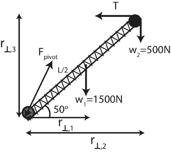
For all the forces here, we choose to use the moment arm method. These distances are calculated in part b). The position vector would be along the boom.
b) We need to balance torques first to find the tension, since the force of the pivot is unknown as well. The two weights give clockwise torques, \(\tau_1\) and \(\tau_2\), and the tension gives counterclockwise torque, \(\tau_T\) relative to the pivot point. Thus, equating the clockwise to counterclockwise torques we get:
\[\tau_1+\tau_2=\tau_T\nonumber\]
Using the \(r_{\perp}\)s drawn in the extended FBD we get:
\[r_{1,\perp}w_1+r_{2,\perp}w_1=r_{3,\perp}T\nonumber\]
Let the length of the boom be \(L\) which results in:
\[\frac{L}{2}\cos 50^{\circ}\times 1500N+L\cos 50^{\circ}\times 500N=L\sin 50^{\circ}\times T\nonumber\]
The distance \(L\) cancels. Solving for \(T\) we get:
\[T=\frac{\cos 50^{\circ}}{\sin 50^{\circ}}\Big(\frac{1500}{2}+500\Big)=1049 N\nonumber\]
b) Balance forces to calculate the pivot force, \(\vec F_p\). In the x-direction:
\[F_{p,x}-T=0\nonumber\]
Resulting in:
\[F_{p,x}=T=1049~\textrm{N}\nonumber\]
Forces in the y-direction:
\[F_{p,y}-w_1-w_2=0\nonumber\]
\[F_{p,y}=w_1+w_2=1500+500=2000~\textrm{N}\nonumber\]
The magnitude of the pivot force is:
\[F_{p}=\sqrt{1049^2+2000^2}=2258~\textrm{N}\nonumber\]
And the angle is:
\[\theta=\arctan\Big(\frac{2000}{1049}\Big)=62.3^{\circ}\nonumber\]
pointing in the northeast direction.