
7.7: Angular Momentum
- Page ID
- 51949

\( \newcommand{\vecs}[1]{\overset { \scriptstyle \rightharpoonup} {\mathbf{#1}} } \)
\( \newcommand{\vecd}[1]{\overset{-\!-\!\rightharpoonup}{\vphantom{a}\smash {#1}}} \)
\( \newcommand{\dsum}{\displaystyle\sum\limits} \)
\( \newcommand{\dint}{\displaystyle\int\limits} \)
\( \newcommand{\dlim}{\displaystyle\lim\limits} \)
\( \newcommand{\id}{\mathrm{id}}\) \( \newcommand{\Span}{\mathrm{span}}\)
( \newcommand{\kernel}{\mathrm{null}\,}\) \( \newcommand{\range}{\mathrm{range}\,}\)
\( \newcommand{\RealPart}{\mathrm{Re}}\) \( \newcommand{\ImaginaryPart}{\mathrm{Im}}\)
\( \newcommand{\Argument}{\mathrm{Arg}}\) \( \newcommand{\norm}[1]{\| #1 \|}\)
\( \newcommand{\inner}[2]{\langle #1, #2 \rangle}\)
\( \newcommand{\Span}{\mathrm{span}}\)
\( \newcommand{\id}{\mathrm{id}}\)
\( \newcommand{\Span}{\mathrm{span}}\)
\( \newcommand{\kernel}{\mathrm{null}\,}\)
\( \newcommand{\range}{\mathrm{range}\,}\)
\( \newcommand{\RealPart}{\mathrm{Re}}\)
\( \newcommand{\ImaginaryPart}{\mathrm{Im}}\)
\( \newcommand{\Argument}{\mathrm{Arg}}\)
\( \newcommand{\norm}[1]{\| #1 \|}\)
\( \newcommand{\inner}[2]{\langle #1, #2 \rangle}\)
\( \newcommand{\Span}{\mathrm{span}}\) \( \newcommand{\AA}{\unicode[.8,0]{x212B}}\)
\( \newcommand{\vectorA}[1]{\vec{#1}} % arrow\)
\( \newcommand{\vectorAt}[1]{\vec{\text{#1}}} % arrow\)
\( \newcommand{\vectorB}[1]{\overset { \scriptstyle \rightharpoonup} {\mathbf{#1}} } \)
\( \newcommand{\vectorC}[1]{\textbf{#1}} \)
\( \newcommand{\vectorD}[1]{\overrightarrow{#1}} \)
\( \newcommand{\vectorDt}[1]{\overrightarrow{\text{#1}}} \)
\( \newcommand{\vectE}[1]{\overset{-\!-\!\rightharpoonup}{\vphantom{a}\smash{\mathbf {#1}}}} \)
\( \newcommand{\vecs}[1]{\overset { \scriptstyle \rightharpoonup} {\mathbf{#1}} } \)
\(\newcommand{\longvect}{\overrightarrow}\)
\( \newcommand{\vecd}[1]{\overset{-\!-\!\rightharpoonup}{\vphantom{a}\smash {#1}}} \)
\(\newcommand{\avec}{\mathbf a}\) \(\newcommand{\bvec}{\mathbf b}\) \(\newcommand{\cvec}{\mathbf c}\) \(\newcommand{\dvec}{\mathbf d}\) \(\newcommand{\dtil}{\widetilde{\mathbf d}}\) \(\newcommand{\evec}{\mathbf e}\) \(\newcommand{\fvec}{\mathbf f}\) \(\newcommand{\nvec}{\mathbf n}\) \(\newcommand{\pvec}{\mathbf p}\) \(\newcommand{\qvec}{\mathbf q}\) \(\newcommand{\svec}{\mathbf s}\) \(\newcommand{\tvec}{\mathbf t}\) \(\newcommand{\uvec}{\mathbf u}\) \(\newcommand{\vvec}{\mathbf v}\) \(\newcommand{\wvec}{\mathbf w}\) \(\newcommand{\xvec}{\mathbf x}\) \(\newcommand{\yvec}{\mathbf y}\) \(\newcommand{\zvec}{\mathbf z}\) \(\newcommand{\rvec}{\mathbf r}\) \(\newcommand{\mvec}{\mathbf m}\) \(\newcommand{\zerovec}{\mathbf 0}\) \(\newcommand{\onevec}{\mathbf 1}\) \(\newcommand{\real}{\mathbb R}\) \(\newcommand{\twovec}[2]{\left[\begin{array}{r}#1 \\ #2 \end{array}\right]}\) \(\newcommand{\ctwovec}[2]{\left[\begin{array}{c}#1 \\ #2 \end{array}\right]}\) \(\newcommand{\threevec}[3]{\left[\begin{array}{r}#1 \\ #2 \\ #3 \end{array}\right]}\) \(\newcommand{\cthreevec}[3]{\left[\begin{array}{c}#1 \\ #2 \\ #3 \end{array}\right]}\) \(\newcommand{\fourvec}[4]{\left[\begin{array}{r}#1 \\ #2 \\ #3 \\ #4 \end{array}\right]}\) \(\newcommand{\cfourvec}[4]{\left[\begin{array}{c}#1 \\ #2 \\ #3 \\ #4 \end{array}\right]}\) \(\newcommand{\fivevec}[5]{\left[\begin{array}{r}#1 \\ #2 \\ #3 \\ #4 \\ #5 \\ \end{array}\right]}\) \(\newcommand{\cfivevec}[5]{\left[\begin{array}{c}#1 \\ #2 \\ #3 \\ #4 \\ #5 \\ \end{array}\right]}\) \(\newcommand{\mattwo}[4]{\left[\begin{array}{rr}#1 \amp #2 \\ #3 \amp #4 \\ \end{array}\right]}\) \(\newcommand{\laspan}[1]{\text{Span}\{#1\}}\) \(\newcommand{\bcal}{\cal B}\) \(\newcommand{\ccal}{\cal C}\) \(\newcommand{\scal}{\cal S}\) \(\newcommand{\wcal}{\cal W}\) \(\newcommand{\ecal}{\cal E}\) \(\newcommand{\coords}[2]{\left\{#1\right\}_{#2}}\) \(\newcommand{\gray}[1]{\color{gray}{#1}}\) \(\newcommand{\lgray}[1]{\color{lightgray}{#1}}\) \(\newcommand{\rank}{\operatorname{rank}}\) \(\newcommand{\row}{\text{Row}}\) \(\newcommand{\col}{\text{Col}}\) \(\renewcommand{\row}{\text{Row}}\) \(\newcommand{\nul}{\text{Nul}}\) \(\newcommand{\var}{\text{Var}}\) \(\newcommand{\corr}{\text{corr}}\) \(\newcommand{\len}[1]{\left|#1\right|}\) \(\newcommand{\bbar}{\overline{\bvec}}\) \(\newcommand{\bhat}{\widehat{\bvec}}\) \(\newcommand{\bperp}{\bvec^\perp}\) \(\newcommand{\xhat}{\widehat{\xvec}}\) \(\newcommand{\vhat}{\widehat{\vvec}}\) \(\newcommand{\uhat}{\widehat{\uvec}}\) \(\newcommand{\what}{\widehat{\wvec}}\) \(\newcommand{\Sighat}{\widehat{\Sigma}}\) \(\newcommand{\lt}{<}\) \(\newcommand{\gt}{>}\) \(\newcommand{\amp}{&}\) \(\definecolor{fillinmathshade}{gray}{0.9}\)Angular Impulse and Momentum
Up to this point, we have developed analogs between linear and angular velocity and acceleration, mass and rotational inertia, and force and torque. Thus, it is only natural to consider the angular analog to linear momentum, known as angular momentum. Since linear momentum is equal to mass times linear velocity, we can make an educated guess that angular momentum is equal to rotational inertia times angular velocity. But let us develop a mathematical definition for angular momentum. To do that, first let's define angular impulse, \(\textrm{ang}~\vec J\), which is analogous to linear impulse:
\[\textrm{ang}~\vec J \equiv \int\limits_{t_i} ^{t_f} \vec\tau dt \]
Following a similar procedure to Equation 7.1.3 and using Equation 7.5.1 we find that:
\[\begin{array}{l}\textrm{ang}~ \vec J && = && \int\limits_{t_i} ^{t_f} \vec\tau dt \\ && = && \int\limits_{t_i} ^{t_f} (I\vec\alpha) dt \\ && = && \int\limits _{t_i} ^{t_f} \Big(I\frac{d\vec\omega}{dt}\Big) dt \\ && = && I\Delta\vec\omega\Big |_{t_i}^{t_f} \\ &&= && I\vec\omega_f-I\vec\omega_i \end{array} \label{Ja}\]
Defining angular momentum, \(\vec L\):
\[\vec L\equiv I\vec\omega\label{L}\]
We see that the direction of angular momentum is the same as the direction of angular velocity which can be obtained using the right-hand rule. The units of angular momentum are \(N\cdot m\cdot sec\), which is equivalent to \(kg\cdot m^2/ sec\). Combining Equations \ref{Ja} and \ref{L} we get the angular equivalent of the impulse- momentum model:
\[\textrm{ang}~ \vec J=\Delta\vec L\]
Conservation of Angular Momentum
If a system has many parts, its total angular momentum is the vector sum of the angular momenta of all the parts:
\[ L = L_1 + L_2 + L_3 \dots = \sum L_i \]
For a system of particles or objects we can write a model for angular momentum:
\[\textrm{Net external angular impulse}=\textrm{ang }\vec J_{net,ext} = \int\limits_{t_i}^{t_f} \sum \vec\tau_{ext} dt= \Delta\vec L_{\textrm{system}}\]
A system acted on by external torque undergoes a change in total angular momentum equal to the net angular impulse (total angular impulse) of the external torques. We can rephrase the relationship stated above as a conservation principle for the total angular momentum of a system of particles:
Conservation of Angular Momentum
If the net external angular impulse acting on a system is zero, then there is no change in the total angular momentum of that system. Otherwise, the change in angular momentum is equal to the net external angular impulse.
This statement is an expression of conservation of angular momentum. As for linear momentum, total angular momentum of a system of objects remains constant as long as there is no net angular impulse due to torques that arise from interactions with objects outside the system.
Analog of Linear and Angular Momentum
We will consider the angular momentum of both a point object as well as the angular momentum of extended objects. In either case, we need to be clear about the axis (or reference point) about which we are calculating the angular momentum. Let us start with a point particle moving in a circle, as the blue particle in Figure 7.7.1.
Fig 7.7.1: Angular and Linear Momentum
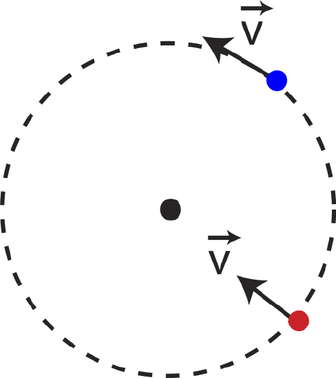
If the particle with mass, \(m\) and speed, \(v\), its linear momentum is, \(\vec p=m\vec v\). The angular momentum of the particle is then:
\[\vec L=I\vec\omega=mr^2\frac{\vec v}{r}=mr\vec v=r\vec p\]
However, ff we consider the red particle instead, which is moving with the same speed but toward the center of the circle, it has no angular momentum relative to the center of the circle. Thus, even though the red particle has the same linear momentum as the blue one, it has zero angular momentum relative to the center of the circle, since there is no change in angle relative to the center. Generally, what matters when defining angular momentum is the component of the momentum which is perpendicular to the line that connects some reference point (such as the center of the circle):
\[L=r\vec p_{\perp}\label{L-point}\]
Since the velocity of the red particle is parallel to the line connecting the center and the particle, its angular momentum is zero. This discussion is starting to seem very similar to the one on torque in Section 7.5. In fact Equation \ref{L-point} looks analogous to Equation 7.5.6, when we were developing the connection between torque and force. Thus, it is no surprise that the general connection between linear and angular momentum has the form analogous to Equation 7.5.7:
\[\vec L=\vec r\times\vec p\]
Alert
Angular motion should not be interpreted as circular motion. Objects do not need to be rotating or moving in a circle in order to have angular velocity and momentum. Angular velocity is defined as a rate of change of angle which is defined relative to some chosen reference point. If there is a change of angle relative to this reference point as the object moves, then it have angular velocity and momentum, even if it is moving in a straight line.
An interesting consequence of this is that a particle that moves in a straight line can have non-zero angular momentum. Figure 7.7.2 shows a particle moving in a straight line with a reference point defined. As the particle moves the angle \(\theta\) will change, so the particle has angular velocity, and thus angular momentum relative to this reference point.
Fig 7.7.2: Angular and Linear Momentum
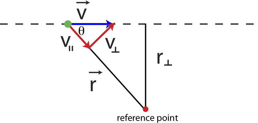
As we just argued in Equation \ref{L-point}, only the perpendicular component of velocity to vector \(\vec r\), \(v_{\perp}\), (depicted in Figure 7.7.2) will contribute to angular momentum. As the particle moves and the angle changes, \(v_{\perp}\) will change as well since \(v_{\perp}=v\sin\theta\). Rewriting Equation \ref{L-point} we get:
\[L=r\vec p_{\perp}=rmv\sin\theta\label{L-gen}\]
The distance \(r\) changes with angle, making Equation \ref{L-gen} difficult to use, but there is a useful simplification. Notice that the distance marked \(r_{\perp}\) in Figure 7.7.2 does not change as the particle moves, and it can related to distance \(r\) as \(r=r_{\perp}\sin\theta\). Equation \ref{L-gen} can the be simplified as:
\[L=rmv\sin\theta=mvr_{\perp}\]
Let us explore some of these connections between linear and angular motion using a concrete example shown below in Figure 7.7.3. In this scenario two astronauts are holding on to a rope of length \(L\) while rotating in space in a clockwise direction, as shown. We want to analyze what happens to angular and linear momentum and velocities when the two astronauts get closer to each other by pulling in the rope, such that the length of the rope between them decreases by half. For simplicity, let us assume that the rope is nearly massless, and that the two astronauts have the same mass, \(m\). We also assume that the astronauts are in empty space with no other external forces present. No forces also implies not external torques are present.
Fig 7.7.3: Angular and Linear Momentum Example
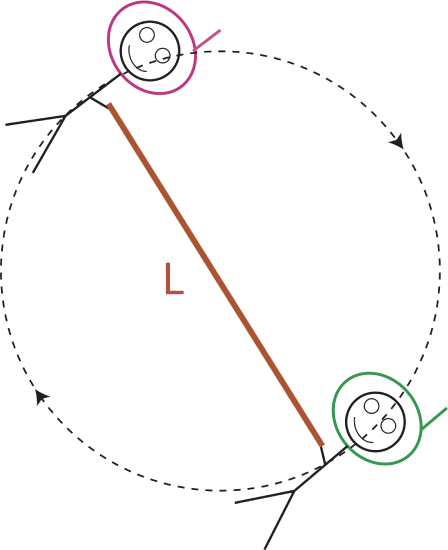
When the two astronauts change the length of the rope, both linear and angular momentum of the two-astronaut system is conserved since there is no net force or torque. For linear momentum, since the two astronauts are across from each other, their velocities will be always in opposite direction, and the combined momentum is zero. In other words, the center of mass of system remains stationary. Thus, for linear momentum:
\[\vec p_{tot}=\vec p_1+\vec p_2=m|\vec v|-m|\vec v|=0=\vec p_f\]
Angular momentum is conserved as well:
\[\vec L_{i}=\vec L_{f}\label{L-cons}\]
We can treat the two-astronaut system as two point masses rotating about their center of mass. The rotational inertia of this system is then:
\[I=\sum mr^2=2mr^2\]
where \(r\) is the distance from the center to each astronaut. Initially when the rope is length \(L\) the rotational inertia is:
\[I_i=2m\Big(\frac{L}{2}\Big)^2=\frac{mL^2}{2}\]
When the astronauts get closer to each other shortening the rope by half, the distance from the center becomes \(L/4\) and the rotational inertia changes to:
\[I_f=2m\Big(\frac{L}{4}\Big)^2=\frac{mL^2}{8}\]
We can rewrite the conservation of angular momentum Equation \ref{L-cons} as:
\[I_i\omega_{i}=I_f\omega_{f}\]
Inserting the results for initial and final rotational inertia, we get:
\[\frac{mL^2}{2}\omega_{i}=\frac{mL^2}{8}\omega_{f}\]
Solving for final angular speed:
\[\omega_f=4\omega_i\label{ang-i-f}\]
The astronauts are spinning four times as fast because they changed the rotational inertia of the system by bringing their masses closer to the center of rotation. This is a very interesting results which does not have a direct analogy for linear momentum. We have a situation where angular momentum is conserved, the system did not change into separate objects, yet the speed changed because the system changed its rotational inertia.
This is exactly the reason why figure skaters spin faster when they pull their arms toward their bodies, decreasing rotational inertial while increasing rotational speed in order to conserve angular momentum. When an ice skater begins to spin with a leg extended, there is only a small torque exerted on the skater by the ice. Thus, angular momentum diminishes rather slowly (she can spin for a long time). Now, if she pulls in her leg, her rotational inertia is reduced considerably, and her rotational velocity (spin velocity) increases considerably. This is most easily seen by writing the angular momentum as \( L = I\omega\) and noting that if \(L\) remains almost constant, then the product \(I\omega\) must remain constant.
Since angular speed changes, so does linear speed. Relating angular and linear velocity:
\[\omega_i=\frac{v_i}{L/2}\]
\[\omega_f=\frac{v_f}{L/4}\]
Using the above equation and Equation \ref{ang-i-f} we find the relationship between initial and speeds for each astronaut:
\[v_f=2v_i\]
To maintain the same angular momentum the linear momentum according to Equation \ref{L-point} had to increase by half since the distance \(r\) decreased by half.
Example \(\PageIndex{1}\)
Pictured is a gaucho, an Argentinian “cowboy”. In his hand he is holding bolas (aka boleadoras), a commonly used throwing weapon among the gauchos. A bolas consists of three equal masses, \(m\), each tied to a rope with length, \(L\), and the three ropes are tied in a knot. You may ignore the mass of the three ropes and the knot in this problem.
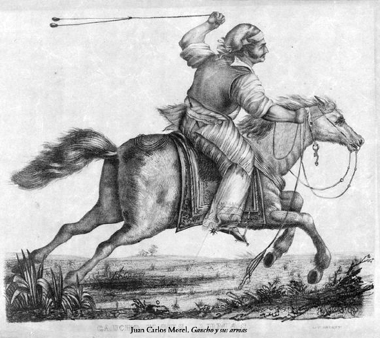
A detailed illustration of bolas and the two different configurations you will analyze is shown here:
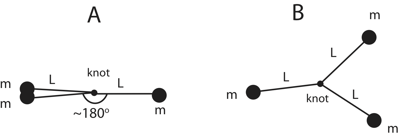
a) Imagine two gauchos Juan and Carlos are each swinging a bolas above their heads. Juan is holding it by one of the masses such that the bolas form a shape as in picture in above A (assume the three ropes form a straight line). Carlos is holding it by the knot. If both gauchos start swinging their bolas at the same time and apply the same torque for 5 seconds, whose bolas will be rotating faster or will they rotate at the same rate?
b) When used as a throwing weapon, a gaucho holds the bolas by one of the balls. He swings the bolas above his head and releases it. Once released the bolas rotate about their center of mass located at the knot. Calculate the final angular velocity given that once released the bolas are rotating at 3 rev/sec. You may neglect the effects of gravity in this interval.
- Solution
-
a) The change in angular momentum is the same for both situations since angular impulse is the same (equal torque applied for the same duration of time). Since the bolas start at rest, both Juan and Carlos's bolas will have the same final angular momentum magnitude of \(L_f= I\omega\). Thus, the one with smaller rotational inertia will be rotating faster. To find rotational inertia use:
\[I=\sum_i(m_ir_i^2)\nonumber\]
For Juan's bolas, the axis of rotation is about one of the masses, scenario A pictured above. So the reference point for the rotational inertia calculation is one of the masses, with the two other masses being a distance 2L away:
\[I_J=(2m)(2L)^2=8mL^2\nonumber\]
For Carlos's bolas, the axis of rotation is about the knot, scenario B pictured above. Each mass is a distance L away from the axis of rotation:
\[I_C=3mL^2\nonumber\]
Since Carlos’s bolas have a smaller rotational inertia, they will be rotating faster after 5 seconds.
b) We assume that there are no external torques, so the initial angular momentum must equal the final angular momentum:
\[\vec L_i=\vec L_f\nonumber\]
\[I_i\omega_i=I_f\omega_f\nonumber\]
The initial rotational inertia is about one of the balls and the final is about the knot which we calculated in part a):
\[(8mL^2)\omega_i=(3mL^2)\omega_f\nonumber\]
Solving for the final angular speed we get:
\[\omega_f=\frac{8}{3}\omega_i=\frac{8}{3}(3~\textrm{rev/s})=8~\textrm{rev/s}=16\pi~\textrm{rad/s}\nonumber\]
Example \(\PageIndex{2}\)
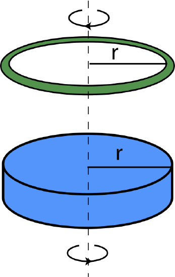
Shown below is a disk which is rotating counterclockwise, as viewed from above, with angular speed of 6 rad/sec, and a ring which is rotating clockwise, as viewed from above, with angular speed of 4 rad/sec. Both are rotating about their center. The ring and the disk have the same radius, \(r\). The ring then drops onto the disk, after which they stick together and continue spinning together counterclockwise, as viewed from the top, with angular speed of 2 rad/sec. Assume that no external torques act on the disk/ring system.
a) Determine which object, the disk or the ring, has a greater magnitude of angular momentum before the collision.
b) Determine the ratio of the mass of the ring over the mass of the disk, \(m_r/m_d\).
c) You would like to stop the rotating disk/ring system. You do think by spinning another ring which is identical to the first one and dropping it onto the system. How fast should you spin the ring and in what direction?
- Solution
-
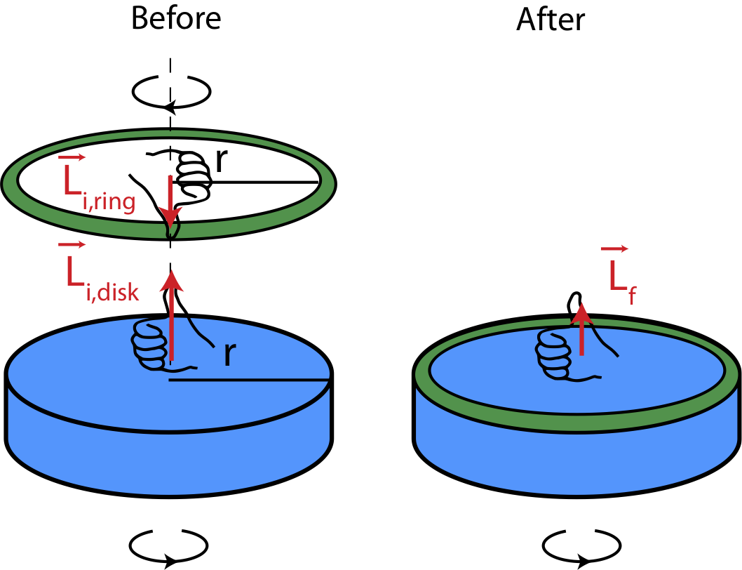
a) The figure below illustrates the initial and final configurations of this system. Using RHR, we see that the angular momentum points upward for the disk and downward for the ring. The initial total angular momentum has to equal to the final total angular momentum, since there are no external torques present. Since the final momentum point upward, this means that the sum of the initial angular momenta has to point upward. For this to be true, the magnitude of the ring's initial angular momentum has to be smaller than the magnitude of the disk's initial angular momentum.
\[\vec L_{tot,i}=\vec L_{tot,f}\nonumber\]
Let us assume that angular momentum is positive when it points up:
\[|\vec L_{i,d}|-|\vec L_{i,r}|=|\vec L_{tot,f}|\nonumber\]
Resulting in:
\[|\vec L_{i,d}|>|\vec L_{i,r}|\nonumber\]
a) Following up from equation in a) we can write the conservation of angular momentum equation as:
\[I_d\omega_{i,d}-I_r\omega_{i,r}=(I_d+I_r)\omega_f\nonumber\]
Looking up the rotational inertia in Section 7.4 for the disk and the ring rotating about their center, and setting the radii equal to each other, \(r_d=r_r=r\), we get:
\[\frac{1}{2}m_dr^2\omega_{i,d}-m_rr^2\omega_{i,r}=\Big(\frac{1}{2}m_dr^2+m_rr^2\Big)\omega_f\nonumber\]
Dividing each side of the equation by \(m_d\) to get the ratio of masses and canceling the factor of \(r^2\) we get:
\[\frac{1}{2}\omega_{i,d}-\frac{m_r}{m_d}\omega_{i,r}=\Big(\frac{1}{2}+\frac{m_r}{m_d}\Big)\omega_f\nonumber\]
The rest of the calculation involves algebraically solving for the ratio. Let's start by moving all the terms containing the mass ratio to the left-side and the remaining terms to the right side:
\[-\frac{m_r}{m_d}(\omega_{i,r}+\omega_f)=\frac{1}{2}(\omega_f-\omega_{i,d})\nonumber\]
Moving the minus sign and solving for the ratio we get:
\[\frac{m_r}{m_d}=\frac{1}{2}\Big[\frac{\omega_{i,d}-\omega_{f}}{\omega_{i,r}+\omega_f}\Big]=\frac{1}{2}\Big[\frac{6-2}{4+2}\Big]=\frac{1}{3}\nonumber\]
c) In order the system to spot the final angular momentum must be zero, so the sum of the new ring's initial momentum and the combined disk/ring system must add up to zero:
\[\vec L_{tot,i}=vec L_{i,r}+\vec L_{i,rd}=\vec L_{tot,f}=0\nonumber\]
For this to be true the direction of the new ring's momentum has to be in the opposite direction, so the ring must be rotating clockwise as seen from above. And the magnitudes must be equal:
\[|\vec L_{i,r}|=|\vec L_{i,rd}|\nonumber\]
Rewriting angular momentum in terms of rotational inertia and angular speed we get:
\[m_rr^2\omega_{i,r}=\Big(\frac{1}{2}m_dr^2+m_rr^2\Big)\omega_{i,rd}\nonumber\]
Solving for \(\omega_{i,r}\) and using the result from b) of the ratio of masses, we get:
\[\omega_{i,r}=\Big(\frac{1}{2}\frac{m_d}{m_r}+1\Big)\omega_{i,rd}=\Big(\frac{1}{2}\times 3+1\Big)(2~\textrm{rad/s})=5~\textrm{rad/s}\nonumber\]
A Special System
There are some fascinating aspects of angular motion. One that we have already encountered is that when rotational inertia is changed by either changing the shape of the rotating object or the rotational axis, it can effect the rotational speed. For example, a diver spins faster when she pulls her body in. Another interesting example is somewhat analogous to a ball moving in a horizontal circle at a constant speed. In that case, linear momentum of the ball, which is tangent to the circle, is always perpendicular to the force by the string pulling toward the center of the circle. As a result, the force changes the direction of momentum while keeping its magnitude constant. For rotation motion, we will look at a situation where the torque is perpendicular to angular momentum.
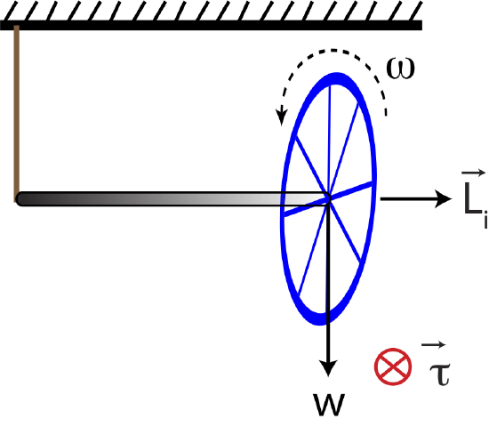
Figure 7.7.4 shows a bicycle wheel supported by a rope attached to the ceiling at the left end of a short axle. The torque caused by the gravitational force acting down at the center of gravity of the wheel produces a torque that points into page, by the right-hand rule. If the wheel is not spinning, it will just fall rotating about the pivot point at the location of the rope, since this is the only point of support. However, if the wheel is initially spinning before being hung by the rope, the situation is much different. Figure 7.7.4 below show a wheel spinning counterclockwise as seen from the right, resulting in angular momentum, labeled \(\vec L_i\), pointing to the right.
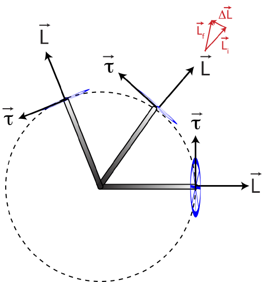
Since torque points into the board, it's easier to visualize all the vectors from the top view. Figure 7.7.5 is a top view of the rotating wheel, where initially the wheel's axle is horizontal resulting in torque pointing up in this view. Our goal is to figure out how this torque will change the wheel's angular momentum as some later time. When torque acts for a time \(\Delta t\), the angular impulse equation gives us the change in angular momentum,
\[\vec\tau \Delta t= \Delta\vec L =\vec L_f-\vec L_i \]
To see what the wheel will do at some later time, it is more convenient to solve the final momentum:
\[\vec L_f =\vec L_i +\vec \tau\Delta t \]
Since torque is perpendicular to the initial angular momentum, instead of slowing down or speeding up the rotational speed it acts to change its direction only, as seen by the vector addition in the figure below. That is, the direction of the initial angular momentum, \(\vec L_i\), is changed by the presence of the angular impulse, and is moved to the direction shown by \(\vec L_f\). This turning motion of the orientation of the wheel is called precession. Instead of falling, the wheel precesses. Once the angular momentum (and the wheel) point in a new direction, the torque comes into play again, causing the wheel to precess still farther. The wheel continues to rotate in a horizontal circle with torque always pointing tangent to the circle and angular momentum pointing outward from the center, in this example of counterclockwise rotation as viewed from the side. In this fashion, the wheel is caused to precess in a horizontal circle about the pivot point. This is the weird behavior exhibited by a spinning top or gyroscope.
Figure 7.7.5: Top View of a Spinning Wheel
Precession is analogous to the situation of a ball being twirled around in a circle on the end of a string. Why doesn’t the tension in the string pull the ball in toward the center of the circle? The answer is that it does, but the large tangential velocity also moves the ball in a direction tangent to the circle. The net result is that the ball travels in a circular path. If there were no large tangential velocity, the ball would indeed be pulled directly toward the center of the circle due to the tension in the string. A similar thing happens with the bike wheel. The torque causes a change in the direction of the large angular momentum of the spinning wheel. If the wheel did not have this large angular momentum, the torque would cause the wheel to tip over or fall down. Keep in mind, we did this analysis assuming friction is negligible. Presence of friction would slow down the rotational speed, and the wheel would eventually fall.